Impedance measuring component, impedance measuring device and impedance measuring method
A technology of impedance measurement and impedance measurement, which is applied in the direction of measuring devices, measuring electrical variables, measuring resistance/reactance/impedance, etc., can solve the problems of large difference in impedance value and unstable impedance value, and achieve small difference in impedance value, Improve stability, ensure stability and accuracy effects
- Summary
- Abstract
- Description
- Claims
- Application Information
AI Technical Summary
Problems solved by technology
Method used
Image
Examples
Embodiment 1
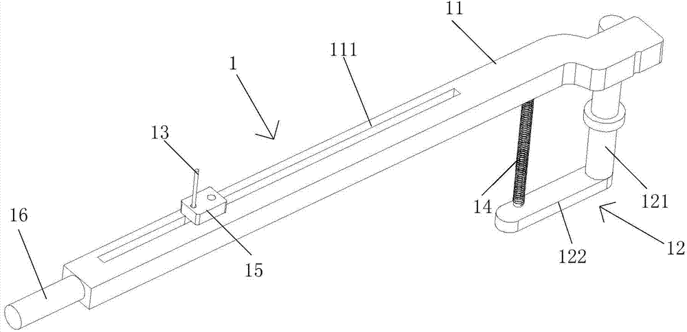
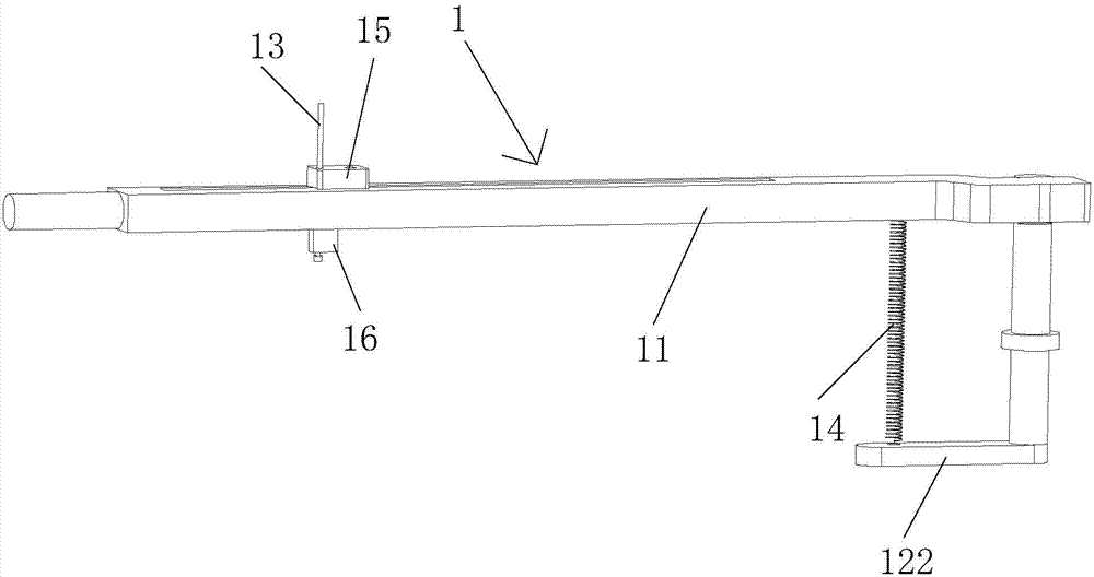
[0095] Figure 1-2 An impedance measurement assembly 1 is shown, and the impedance measurement assembly 1 includes: a pressing rod 11 , a connecting shaft 12 and a first probe 13 . Wherein, the connecting shaft 12 is connected to one end of the pressing rod 11 . The first probe 13 is fixed on the pressing rod 11, and one end of the first probe 13 is used to electrically connect with the electrode of the impedance measuring instrument 3. When the pressing rod 11 is depressed, the The other end of the first probe 13 is used for electrical connection with the measurement point of the object 4 to be measured. Of course, in actual use, the top of the connecting shaft 12 is connected to one end of the pressing rod 11 .
[0096] In this embodiment, the pressure rod 11 can be rotated on the vertical plane to ensure that the first probe 13 is fully in contact with the measurement point of the object to be measured 4, and while realizing a reliable electrical connection, it is also gu...
Embodiment 2
[0110] Such as Figure 3-5 As shown, this embodiment provides an impedance measurement device, please combine Figure 1-2 It should be understood that the impedance measurement device includes two sets of impedance measurement components 1 as described in Embodiment 1 and a bracket 2 . The connecting shafts 12 of the two sets of impedance measuring components 1 are arranged at intervals and are fixed on the support 2, and the connecting shafts 12 of at least one set of impedance measuring components 1 are rotating shafts. Of course, in actual use, the connecting shafts 12 of the two sets of impedance measuring assemblies 1 are rotating shafts.
[0111] In this embodiment, two sets of impedance measurement components 1 are arranged on a support 2, and their connecting shaft 12 can rotate on the plane where the measurement surface of the object to be measured 4 is located, so that the object to be measured 4 can be placed on At the same time, the position of the pressure bar 1...
Embodiment 3
[0125] The structure of the impedance measurement device of the present embodiment is basically the same as that of the embodiment 2, and it also includes two sets of impedance measurement components as described in the embodiment 1. The difference is that the impedance measurement The apparatus also includes a conductor and a placement table. Wherein, an accommodating groove is opened in the bracket, and the conductor is placed in the accommodating groove. Certainly, in this embodiment, the accommodating groove is located in the top plate of the bracket.
[0126] At the same time, the bracket is provided with a placing platform, and the placing platform covers the top surface of the conductor. In addition, a plurality of positioning holes for penetrating the second probes are opened on the placing platform, one end of the second probes is electrically connected to the conductor, and the other end is used for electrical connection with the measuring point of the object to be ...
PUM
 Abstract
Description
Claims
Application Information
 - R&D
- Intellectual Property
- Life Sciences
- Materials
- Tech Scout
- Unparalleled Data Quality
- Higher Quality Content
- 60% Fewer Hallucinations
Browse by: Latest US Patents, China's latest patents, Technical Efficacy Thesaurus, Application Domain, Technology Topic, Popular Technical Reports.
© 2025 PatSnap. All rights reserved.Legal|Privacy policy|Modern Slavery Act Transparency Statement|Sitemap|About US| Contact US: help@patsnap.com


