micro torque tool

A torque tool and a tiny technology, applied in the field of tiny torque tools, can solve the problems of wear and tear of the wrist and palm, tingling of the user, and the screw of the screw lock cannot reach the torque setting value, etc., saving screwing time and convenience. Easy to apply force

Active Publication Date: 2016-06-08
胡厚飞
View PDF10 Cites 0 Cited by
  • Summary
  • Abstract
  • Description
  • Claims
  • Application Information

AI Technical Summary

Problems solved by technology

[0002] Referring to the U.S. Patent No. US7281457 "Wrenchwithadjustablemaximumoperationaltorque" patent case, it is a tiny torque wrench with adjustable torque. When checking the torque value, the user will find that it is difficult to continue to increase the force applied to the torque wrench simply by using fingers, so the screw cannot be further tightened, so that the screw that is screwed cannot reach the required torque setting value. question
[0003] In order to solve the above problems, users usually try to hold the torque wrench with the entire palm of their hand as much as possible, hoping to increase the turning force. It is difficult to fully transmit the force to the torque wrench, which leads to the loss of force applied to the wrist and palm, and even makes the user feel tingling or discomfort in the palm. Finally, the user can only turn the torque wrench with both hands at the same time to make the screw possible. Achieve the result of real locking to the required set torque value
[0004] However, the two-handed operation also constitutes a trouble for the user. The alternating process of one-handed operation and two-handed operation has formed an inconvenient result, which in turn affects consumers' desire to purchase this product, and greatly damages the goodwill of the product.

Method used


Image

  • micro torque tool
  • micro torque tool
  • micro torque tool

Examples


Embodiment Construction

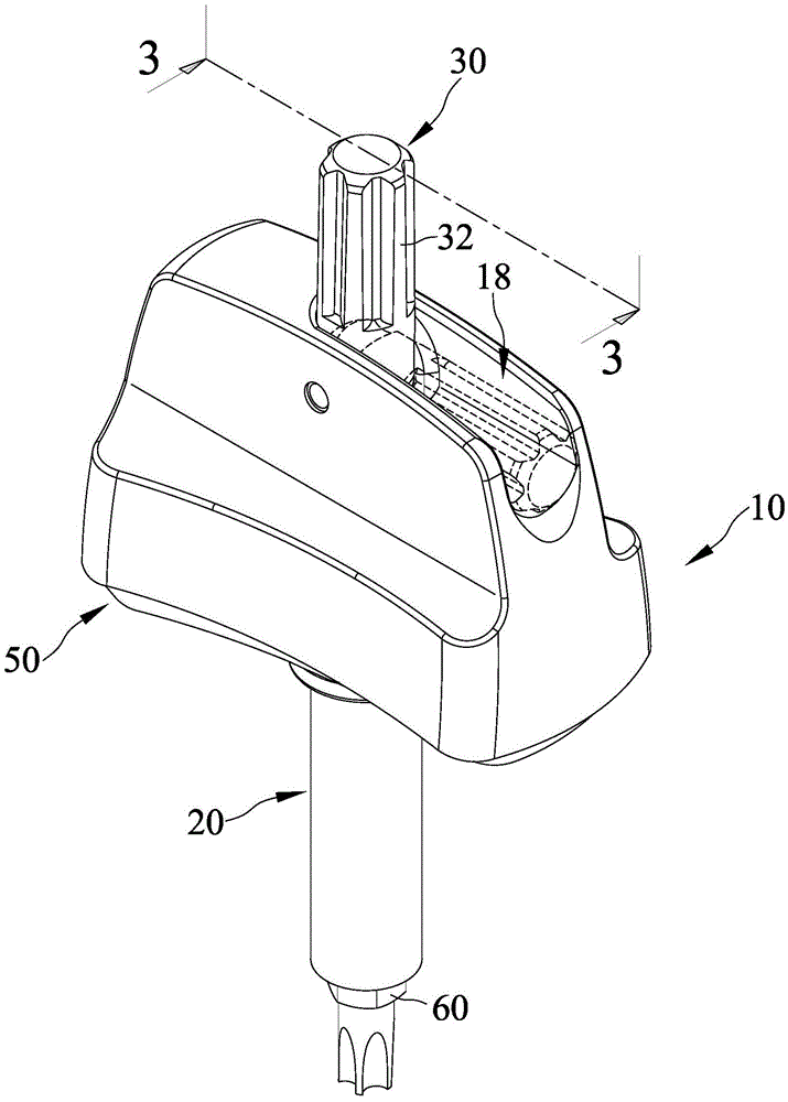
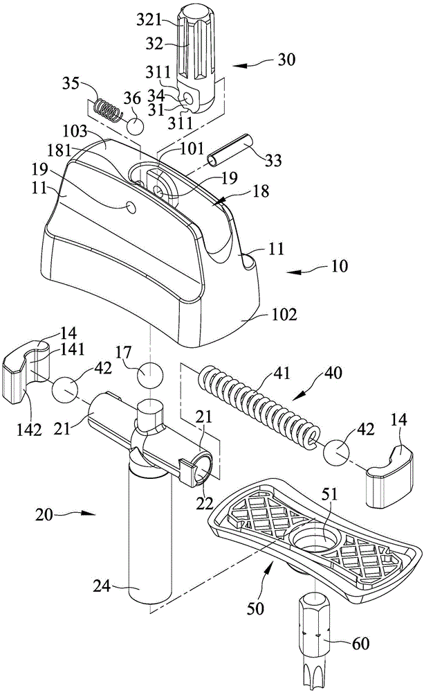
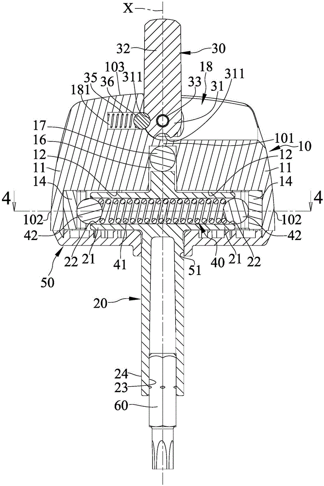
[0038]refer to figure 1 and figure 2 , the micro torque tool of the present invention comprises a body 10, a driving rod 20 pivotally arranged in the body 10, a rotating rod 30 connected to the top of the body 10, and a rotating rod 30 arranged in the driving rod 20 and pushed against the The bouncing device 40 of the body 10 and the rotating rod 30 can move between the coaxial position and the storage position. When the rotating rod 30 is in the coaxial position, the rotating rod 30 can be quickly rotated by the user's fingers to achieve fast screw rotation of the work object. 90 (see Figure 5 ), when the rotating rod 30 is in the storage position, the user's palm will not be hindered by the rotating rod 30 and can fully hold the body 10, so as to achieve the effect of twisting the working object 90 to the set torque value; wherein:

[0039] Please refer to Figure 2 to Figure 4 , the body 10 has a first end 101 and a second end 102, the first end 101 of the body 10 can ...


PUM


Abstract

The invention provides a small-torque tool. The small-torque tool comprises a body, a driving rod, a rotating rod and an elastic abutting device, wherein the driving rod is arranged in the body in a pivoted manner, the rotating rod is connected to the top end of the body, and the elastic abutting device is arranged in the driving rod and pushes the body; the rotating rod can move between the coaxial position and the storage position; when the rotating rod is at the coaxial position, a user is allowed to rapidly rotate the rod with fingers so as to achieve the effect that a work piece is rapidly rotated in a screw manner; and when the rotating rod is at the storage position, as the palm of the user cannot be obstructed by the rotating rod and can completely hold the body, and the center of the palm can be completely attached to the top edge of the body, force can be conveniently and easily applied, and the force applied with the wrist and the palm can be completely transmitted to the small-torque tool so as to achieve the effect that the work piece is twisted to be in the set torsion value; and the beneficial effect of decreasing the height of the small-torque tool is achieved, and the user can conveniently collect or carry the tool.

Description

technical field [0001] The invention relates to a micro torsion tool, especially a micro torsion tool capable of switching two operation modes. Background technique [0002] Referring to the U.S. Patent No. US7281457 "Wrenchwithadjustablemaximumoperationaltorque" patent case, it is a tiny torque wrench with adjustable torque. When checking the torque value, the user will find that it is difficult to continue to increase the force applied to the torque wrench simply by using fingers, so the screw cannot be further tightened, so that the screw that is screwed cannot reach the required torque setting value. question. [0003] In order to solve the above problems, users usually try to hold the torque wrench with the entire palm of their hand as much as possible, hoping to increase the turning force. It is difficult to fully transmit the force to the torque wrench, which leads to the loss of force applied to the wrist and palm, and even makes the user feel tingling or discomfor...

Claims


Application Information

Patent Timeline
Patent Type & Authority Patents(China)
IPC IPC(8): B25B15/02B25B23/00
CPCB25B15/02B25B23/00
Inventor 胡厚飞张宪仪
Owner 胡厚飞
Why Eureka
Try Eureka