
Touch panel, method of manufacturing touch panel, optical film substrate and method of manufacturing same

A touch panel and substrate technology, applied in the input/output process of optics, optical components, data processing, etc., can solve problems such as deterioration of electric wave characteristics, unsatisfactory, reduced visibility, etc., to maintain shading performance, prevent visible Sex-reducing effect

Active Publication Date: 2018-01-12
ULVAC INC
View PDF13 Cites 0 Cited by
  • Summary
  • Abstract
  • Description
  • Claims
  • Application Information

AI Technical Summary

Problems solved by technology

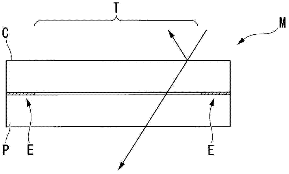
[0011] However, if the non-transmissive light-shielding film th in the edge portion E is formed by printing on the touch panel substrate P side of the cover substrate C so as to have the above-mentioned thickness dimension, the Figure 5 , as shown by Air, there is a gap between the cover substrate C and the touch panel substrate P
According to this, since reflection occurs at the back surface of the cover substrate C and the front surface of the touch panel substrate P, there is a problem that the visibility is reduced, and the decrease in the output of the display unit is hindered by the decrease in visibility.
[0012] Furthermore, as shown in Patent Document 1, when a conductor such as metal is provided on the edge portion E, since the dielectric constant of the cover substrate C or the panel portion P is different from that of the edge portion E, characteristics such as radio characteristics may deteriorate, so it is not necessary to ideal

Method used


Image

  • Touch panel, method of manufacturing touch panel, optical film substrate and method of manufacturing same
  • Touch panel, method of manufacturing touch panel, optical film substrate and method of manufacturing same
  • Touch panel, method of manufacturing touch panel, optical film substrate and method of manufacturing same

Examples


Embodiment Construction

[0046] Next, a touch panel according to an embodiment of the present invention will be described with reference to the drawings.

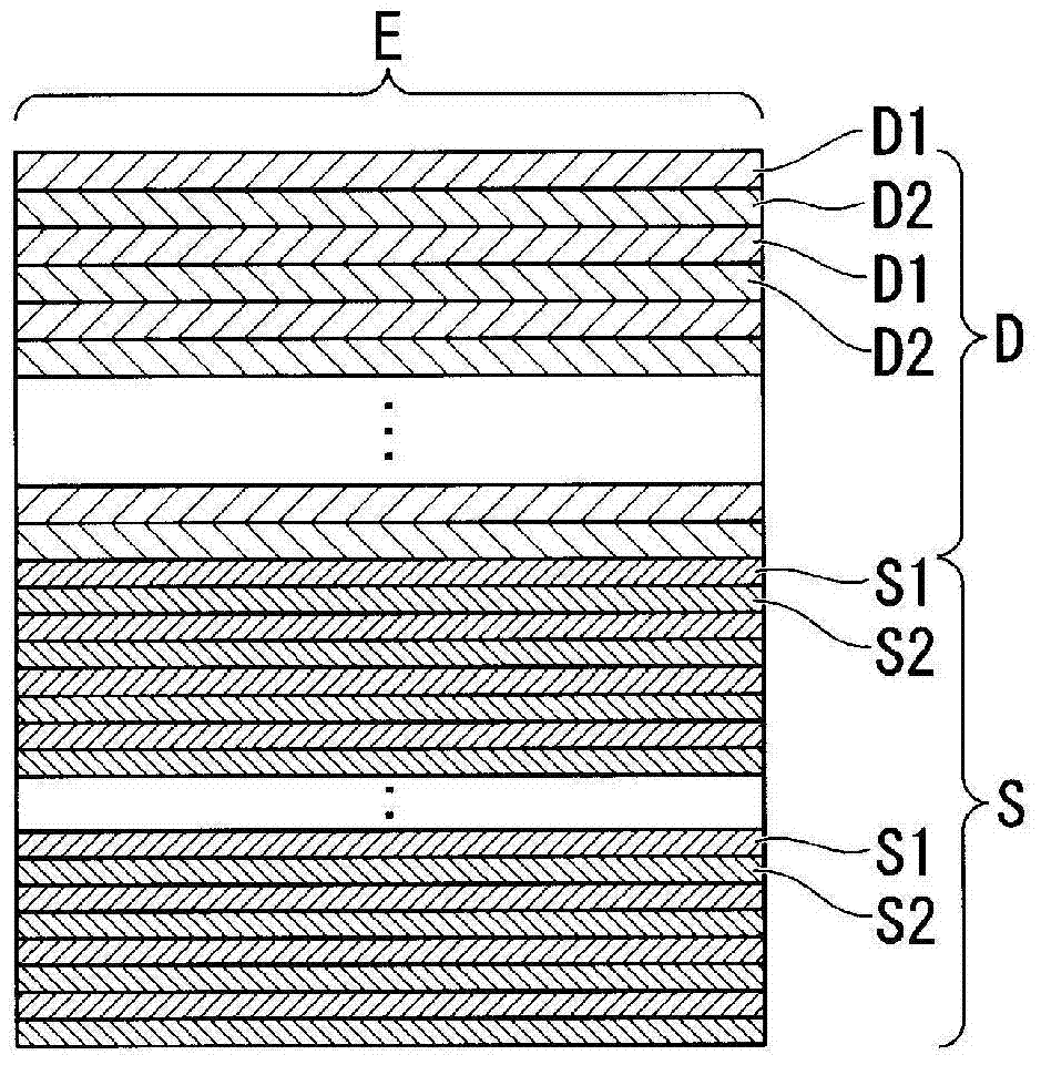
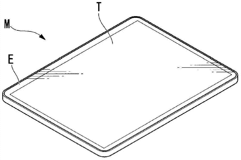
[0047] Figure 1A It is a sectional view showing the touch panel in this embodiment. Figure 1B It is an enlarged view of the edge of the touch panel in this embodiment. figure 2 It is a perspective view showing the touch panel in this embodiment. exist Figure 1A and figure 2 Among them, the symbol M is the touch panel.

[0048] In the touch panel M of the present embodiment, as Figure 1A , figure 2 As shown, a touch panel substrate P having a display region T capable of display and touch operations and a cover substrate C formed of a transmissive substrate such as glass are arranged to overlap. In addition, between the touch panel substrate P and the cover substrate C, in a region excluding the display region T, a connection portion is provided at an edge portion E around the display region T. As shown in FIG.

[0049] The touch panel...


PUM


Abstract

The touch panel of the present invention includes: a cover substrate; a connecting portion provided on the cover substrate in an area other than the display area, including a color layer, and a metal layer and a dielectric body thicker than the metal layer A shielding layer formed of a multilayer structure formed by laminating layers alternately; and a touch panel substrate disposed opposite to the cover substrate so as to intervene in the connecting portion.

Description

technical field [0001] The present invention relates to a technique suitable for use in a touch panel, a method of manufacturing the touch panel, an optical film substrate, and a method of manufacturing the same. [0002] This application claims priority based on Japanese Patent Application No. 2013-145755 for which it applied in Japan on July 11, 2013, and uses the content here. Background technique [0003] In recent years, liquid crystal display devices with touch panels that also function as input devices have been widely used as display devices for various electronic devices including mobile phones and handheld game machines. [0004] Such a touch panel has a touch panel substrate in which a light-transmitting conductive layer and the like are laminated on a transparent substrate and a thin film is laminated and formed on the outermost surface side, and is sensitive to a finger or the like according to a change in electrostatic capacity or the like. The operating posit...

Claims


Application Information

Patent Timeline
Patent Type & Authority Patents(China)
IPC IPC(8): G06F3/041
CPCG06F3/041G02B5/22G02B5/26G02B5/286G06F2203/04103G06F2203/04107
Inventor 原田学井堀敦仁铃木寿弘柳坪秀典松本昌弘久保昌司新井真
Owner ULVAC INC
Learn More