Broadband relativistic klystron amplifier

A relativistic and klystron technology, applied in the field of microwave electronics, can solve the problems of low characteristic impedance of the output cavity, single frequency spectrum, high Q value, etc., and achieve the effects of improving angular uniformity, increasing the number of gaps, and widening the bandwidth

Active Publication Date: 2015-08-12
INST OF APPLIED ELECTRONICS CHINA ACAD OF ENG PHYSICS
View PDF5 Cites 7 Cited by
  • Summary
  • Abstract
  • Description
  • Claims
  • Application Information

AI Technical Summary

Problems solved by technology

At present, in traditional relativistic klystron amplifiers, the structure of single-gap input cavity, inductive intermediate cavity (the frequency of the intermediate cavity is higher than the operating frequency, that is, the intermediate cavity is inductive) and single-gap output cavity is generally used, which affects the relativistic klystron. There are three main factors for the bandwidth of the amplifier: 1. The Q value of the input cavity is high and the characteristic impedance is low, so that the beam bandwidth of the electron beam after passing through the input cavity is not high
2. The number of modulation cavities is small, and in order to increase the modulation current intensity, the frequency of the modulation cavity cold cavity is generally higher than the working frequency (the cavity is inductive), resulting in a narrow beam bandwidth of the RKA grouping section
3. The Q value of the output cavity is large and the characteristic impedance is low, so that the electric field intensity excited by the electron beam in the gap of the output cavity is high, causing part of the electron backflow and radio frequency breakdown to cause the low bandwidth of the output section of the RKA
[0006] In traditional RKA, in order to ensure high output microwave power and single spectrum, a single gap is often used to re-enter the nose cone output cavity, resulting in low characteristic impedance of the output cavity and high Q value, so that the electric field intensity excited by the electron beam in the gap of the output cavity Higher, causing part of the electronic backflow and radio frequency breakdown, affecting the bandwidth of the RKA output microwave

Method used


Image

  • Broadband relativistic klystron amplifier

Examples


Embodiment Construction

[0020] In order to clearly illustrate the technical features of the solution, the solution will be described below through a specific implementation mode combined with the accompanying drawings.

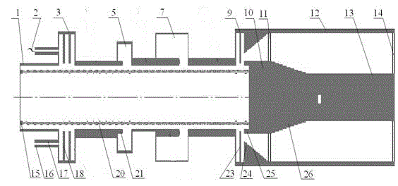
[0021] It can be seen from the drawings that the working principle of this scheme is: the high-frequency signal output by the microwave seed source is fed into the three-gap input cavity and a high-frequency electric field is established on the cavity gap. When the DC electron beam emitted by the cathode passes through the gap of the input cavity under the constraint of the axial magnetic field, the velocity of the electrons is modulated under the action of the high-frequency electric field in the gap of the input cavity, and the electron beam whose velocity is modulated enters the drift tube behind the input cavity Get flocked. When the clustered electron beam passes through the gap between the first intermediate cavity and the second intermediate cavity, a high-frequency induced cu...


PUM


Abstract

The invention provides technical scheme of a broadband relativistic klystron amplifier. The broadband relativistic klystron amplifier comprises an input cavity, an output cavity, a first intermediate cavity, a second intermediate cavity, a first output transition section, a second output transition section, a collector, a supporting rod, an output coaxial line inner conductor and an output coaxial line outer conductor which are arranged on a drift tube. According to the scheme provided by the invention, the multi-interspace input cavity, two irregular frequency tuning intermediate cavities and the multi-interspace output cavity are adopted, and the bandwidth of the relativistic klystron amplifier can be increased by 10%.

Description

technical field [0001] The invention relates to the field of microwave electronics, in particular to a broadband relativistic klystron amplifier. Background technique [0002] Relativistic klystron amplifier (RKA) is one of the most potential high-power microwave generating devices. Because RKA has the advantages of high power, high efficiency, output microwave phase and amplitude stability, it has been widely used in communication, radar, navigation, linear Accelerators, etc. In the field of accelerators, klystrons with high peak power and narrow band work are mainly used. However, in some early warning radar systems, due to the need for anti-jamming, the klystron is required to have a certain working bandwidth, and the bandwidth of the ordinary RKA is not more than 5%, which limits its application range. Therefore, expanding the bandwidth of the relativistic klystron amplifier is One of the key points in RKA research. [0003] The RKA bandwidth is mainly determined by t...

Claims


Application Information

Patent Timeline
IPC IPC(8): H01J25/10H01J23/36H01J23/18
Inventor 雷禄容袁欢黄华刘振帮黄吉金何琥陈昭福
Owner INST OF APPLIED ELECTRONICS CHINA ACAD OF ENG PHYSICS
Why Eureka
Try Eureka