Distributed type energy resource flue gas waste heat deep utilization system

A distributed energy and flue gas waste heat technology, applied in the field of energy systems, can solve problems such as high exhaust gas temperature of waste heat boilers, high heat consumption of energy stations, and insufficient utilization of flue gas waste heat, so as to reduce exhaust gas temperature and improve economic efficiency. Sexuality and the effect of reducing equipment investment

Inactive Publication Date: 2015-08-12
CHINA ENERGY ENG GRP GUANGDONG ELECTRIC POWER DESIGN INST CO LTD
View PDF7 Cites 10 Cited by
  • Summary
  • Abstract
  • Description
  • Claims
  • Application Information

AI Technical Summary

Problems solved by technology

[0005] The purpose of the present invention is to solve the problems of high waste heat boiler exhaust temperature, insufficient utilization of waste heat of flue gas and high heat consumption of energy stations in existing distributed energy stations, and to provide a system for deep utilization of waste heat of distributed energy flue gas

Method used


Image

  • Distributed type energy resource flue gas waste heat deep utilization system

Examples


specific Embodiment 1

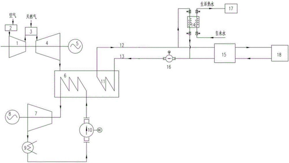
[0018] refer to figure 1 , this embodiment includes a gas turbine generator set, a steam turbine generator set, a waste heat boiler 6, a hot water heat exchanger 11 and water equipment, a gas turbine generator set includes a compressor 1, a combustion chamber 3, a gas turbine 4 and a gas turbine generator 5, The steam turbine generator set includes a steam turbine 7 and a steam turbine generator 8; the exhaust end of the gas turbine 4 is connected to the intake end of the waste heat boiler 6, and the exhaust gas from the waste heat boiler 6 is discharged into the atmosphere to form a waste heat utilization system of the gas turbine generator set; The steam output end of the waste heat boiler 6 is connected to the water inlet end of the waste heat boiler 6 through the steam turbine 7, the condenser 9, and the feed water pump 10 to form a steam engine Rankine cycle power generation circuit; the tail end of the waste heat boiler 6 is provided with a hot water exchange Heater 11, ...

specific Embodiment

[0025] The characteristics of other specific embodiments of the present invention are: on the basis of specific embodiment 1, one of the domestic hot water user 17 and the cold / heat user terminal 18 is omitted. All the other are with specific embodiment 1.


PUM


Abstract

The invention relates to a distributed type energy resource flue gas waste heat deep utilization system. The distributed type energy resource flue gas waste heat deep utilization system comprises a gas turbine generator set, a steam turbine generator set, a waste heat boiler and water utilization equipment, and is characterized in that the exhaust end of a gas turbine is communicated with the gas inlet end of the waste heat boiler, the steam output end of the waste heat boiler is connected with the steam inlet end of a steam turbine to form a gas turbine waste heat utilization loop; the steam outlet end of the steam turbine is connected with the water inlet end of the waste heat boiler sequentially by a condenser and a feed pump to form a steam turbine waste heat utilization loop; the waste heat boiler is provided with a hot water exchanger capable of heating moisture; and the high-temperature hot water output end of the hot water exchanger is connected with the input end of the water utilization equipment, and the low-temperature hot water return input end of the hot water exchanger is connected with the low-temperature hot water return output end of the water utilization equipment to form a distributed type energy resource flue gas waste heat deep utilization structure. The distributed type energy resource flue gas waste heat deep utilization system has the beneficial effects that the temperature of flue gas exhausted by the waste heat boiler is reduced, the flue gas waste heat can be sufficiently utilized, and the energy utilization rate is high.

Description

technical field [0001] The invention relates to a distributed energy waste heat utilization system, in particular to a distributed energy flue gas waste heat deep utilization system, which belongs to the technical field of energy systems. Background technique [0002] Distributed energy is a comprehensive energy utilization system distributed at the user end, pursuing energy cascade utilization to achieve higher energy utilization efficiency. [0003] Distributed energy systems with prime movers as small gas turbines generally use natural gas as fuel, and the main equipment includes gas turbine generators, waste heat boilers, and steam turbine generators. Since the prime mover of this level is generally equipped with a dual-pressure waste heat boiler, the exhaust gas temperature of the waste heat boiler is relatively high, generally about 110-130°C. Flue gas waste heat is a resource with great potential. The high discharge temperature of waste heat boiler flue gas not only ...

Claims


Application Information

Patent Timeline
IPC IPC(8): F02C6/18F01K23/10F25B27/02F24F5/00
CPCY02A30/274
Inventor 印佳敏袁长春黄长华胡江波史磊
Owner CHINA ENERGY ENG GRP GUANGDONG ELECTRIC POWER DESIGN INST CO LTD
Why Eureka
Try Eureka