Discharge unit and air purifier

A discharge unit and discharge wire technology, applied in the direction of air quality improvement, chemical instruments and methods, power supply technology, etc., to achieve the effect of miniaturization and suppression of abnormal discharge

Inactive Publication Date: 2017-03-08
DAIKIN IND LTD
View PDF6 Cites 0 Cited by
  • Summary
  • Abstract
  • Description
  • Claims
  • Application Information

AI Technical Summary

Problems solved by technology

However, with this short-circuit method, it may happen that the cut end of the discharge wire does not touch the electrode plate, and there is no short circuit between the high-voltage power supply and the electrode plate.

Method used


Image

  • Discharge unit and air purifier
  • Discharge unit and air purifier
  • Discharge unit and air purifier

Examples


Embodiment Construction

[0060] Embodiments of the present invention will be described below with reference to the drawings.

[0061] [structure of air cleaner 1]

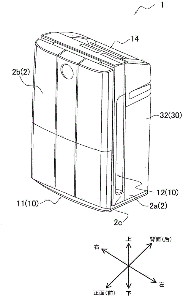
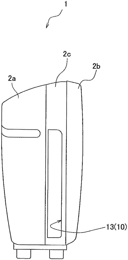
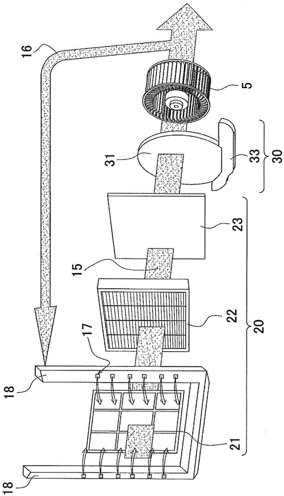
[0062] The air purifier 1 of the embodiment of the present invention is as Figure 1 to Figure 4 As shown, it has: a housing 2 composed of a main body housing 2a and a front panel 2b, an electrical dust collector 3 (discharging unit), a streamer discharge unit (Japanese: ストリーマラニット4, a fan 5, a filter unit 20, a humidifier Unit 30 etc.

[0063] Such as figure 1 As shown, the front of the air cleaner 1 is covered by a front panel 2b. There is a part not covered by the front panel 2b below the front, and the lower suction port 11 is provided in this part. Such as figure 1 and figure 2 As shown, a part of the side surface of the air cleaner 1 is covered with a part of the main body case 2a, that is, a side inlet forming member 2c made of synthetic resin. The first side suction port 12 for sucking in air is formed in the side suction po...


PUM


Abstract

Prior electrical discharge units had the problem that the size of the discharge unit was large because an earth plate was provided separately from the electrode plate. The present electrical discharge unit comprises an electrical discharge wire (51) that is electrically connected to a high voltage power source and an electrode plate (52) that faces the electrical discharge wire (51), and discharges electricity between the electrical discharge wire (51) and the electrode plate (52) by applying a high voltage on the electrical discharge wire (51). Said electrical discharge unit also is provided with a short-circuiting member (62) that is electrically connected to the high voltage power source. The short-circuiting member (62) contacts the electrical discharge wire (51) without contacting the electrode plate (52) and when the electrical discharge wire (51) breaks, contacts the electrode plate (52).

Description

technical field [0001] The present invention relates to a discharge unit that applies a high voltage to a discharge line to discharge between the discharge line and an electrode plate, and an air cleaner including the discharge unit. Background technique [0002] A conventional discharge unit includes a discharge line and an electrode plate facing the discharge line, and a high voltage is applied to the discharge line to discharge between the discharge line and the electrode plate. Such a discharge unit can electrify small dust floating in the air through the discharge, generate an active substance having a bactericidal effect, or generate negative ions emitted into the air. [0003] In the discharge unit, when the discharge wire is disconnected, the cut end of the discharge wire contacts the electrode plate, so that a short circuit occurs between the high-voltage power supply and the electrode plate. However, with this short-circuit method, it may happen that the cut end o...

Claims


Application Information

Patent Timeline
Patent Type & Authority Patents(China)
IPC IPC(8): B03C3/40B03C3/41B03C3/70
CPCB01D53/323B01D2257/404B01D2257/406B01D2257/708B01D2257/90B01D2258/06B03C3/32B03C3/41B03C3/70B03C3/72B03C3/86B03C2201/04F24F8/192F24F8/194Y02A50/20
Inventor 长尾光久山下哲也
Owner DAIKIN IND LTD
Why Eureka
Try Eureka