
Method for the surface treatment of a workpiece

A workpiece surface and surface treatment technology, applied in the direction of cleaning methods using gas flow, heat treatment furnaces, heat treatment equipment, etc., can solve the problem that the blower cannot generate directional compressed airflow, and achieve the effect of reducing environmental and health hazards

Inactive Publication Date: 2015-08-05
THYSSENKRUPP STEEL EURO AG
View PDF9 Cites 6 Cited by
  • Summary
  • Abstract
  • Description
  • Claims
  • Application Information

AI Technical Summary

Problems solved by technology

Another disadvantage is that the blower does not generate a directed compressed air flow but only a swirling air flow with a very low pressure

Method used


Image

  • Method for the surface treatment of a workpiece
  • Method for the surface treatment of a workpiece
  • Method for the surface treatment of a workpiece

Examples


Embodiment Construction

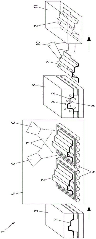
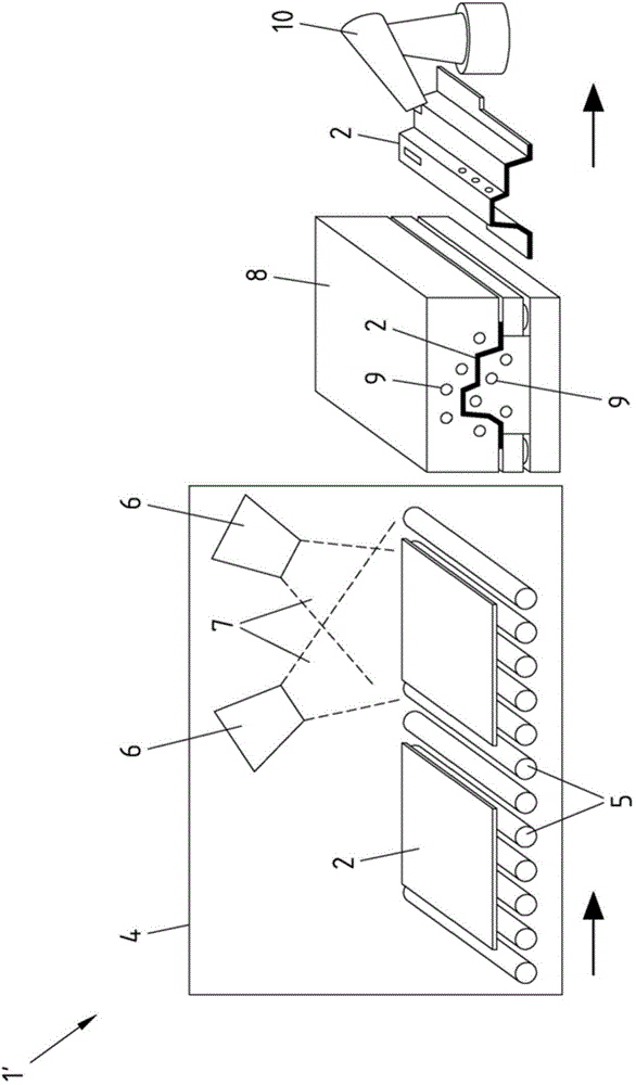
[0025] exist figure 1In , a first version of a device 1 for carrying out the method according to the invention is shown. The device 1 contains a plurality of workstations in which workpieces 2 can be processed or processed one after the other. figure 1 The workpieces 2 involved in the plant 1 shown in are metal sheets or sheets which pass through the plant 1 in the direction of the arrow. exist figure 1 The plant 1 shown in FIG. 1 has a device 3 for cold forming a workpiece 2 as a first work station. The device 3 can be a press in which the workpiece 2 is plastically deformed. The deformed workpiece 2 then enters the furnace 4 as the next station of the plant 1 . exist figure 1 The furnace 4 shown in is a roller hearth furnace in which the deformed workpiece 2 is transported on rollers 5 and heated. Instead of such a roller hearth furnace, it is also possible to install a batch furnace with the workpieces 2 arranged in layers, as is known from DE 10 2010 043 229 A1.

[...


PUM


Abstract

Shown and described herein is a method for the surface treatment of workpieces, in particular of coated metal workpieces, for hot forming. In order to achieve an improved surface treatment of the workpieces, the following steps are proposed: b) partially or completely heating the workpieces to a temperature of at least Ac1, c) cleaning the workpiece surfaces of the heated workpieces with at least one pressurized air jet, d) forming the heated and cleaned workpieces, and e) cooling down the formed workpieces.

Description

technical field [0001] The invention relates to a method for the surface treatment of workpieces, in particular coated metal workpieces for thermoforming. Background technique [0002] Thermoforming is well known and commonly used as a method of plastically deforming metallic materials. In contrast to cold forming, hot forming is carried out at temperatures above the recrystallization temperature of the workpiece to be formed and can therefore achieve very high degrees of deformation. Due to the heating of the workpiece necessary for thermoforming there is the risk that parts of the coating will come off and stick to the heated workpiece as dirt. Such contaminants may damage (extrusion) tools during subsequent thermoforming or degrade the surface quality and dimensional stability of the finished part and should therefore be avoided. [0003] From DE 10 2007 012 180 B3 a method is known for the heat treatment of semi-finished metal products in a continuous furnace. The con...

Claims


Application Information

Patent Timeline
IPC IPC(8): C21D7/13C21D7/02F27B9/10F27B9/24
CPCB08B5/02B21J17/00C21D9/0056C21D1/673B21D22/022B21D22/201B21D22/208
Inventor 马里亚·科耶尔扬科·巴尼克
Owner THYSSENKRUPP STEEL EURO AG
Learn More