A servo tool holder structure and its application method

A servo tool holder and component technology, applied in the direction of manufacturing tools, tool holders, precision positioning equipment, etc., can solve the problems of cumbersome structure, complex motion, and increase the difficulty of tool holder parts assembly, so as to simplify the design and installation The difficulty of debugging and the effect of improving the transmission accuracy

Active Publication Date: 2017-03-01
SHENYANG MASCH TOOL CO LTD
View PDF3 Cites 0 Cited by
  • Summary
  • Abstract
  • Description
  • Claims
  • Application Information

AI Technical Summary

Problems solved by technology

[0004] The purpose of the present invention is to provide a servo tool holder structure and its use method, which solves the complex movement and cumbersome structure of the tool holder positioning and indexing in the prior art, as well as the difficulty of increasing the manufacturing of tool holder parts and the assembly of the whole machine Degree and other issues, to provide tool changing device for CNC lathes

Method used


Image

  • A servo tool holder structure and its application method
  • A servo tool holder structure and its application method
  • A servo tool holder structure and its application method

Examples


Embodiment Construction

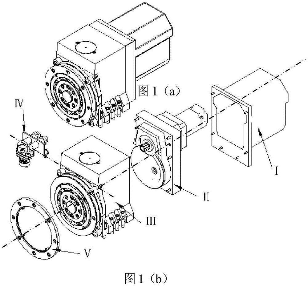
[0033] As shown in Figure 1(a)-(b), Figure 10-1 and Figure 10-2 As shown, the servo tool holder structure of the present invention is applied to CNC lathes and CNC turning centers to realize the tool change function, and mainly includes casing I, rear cover assembly II, box assembly III, proximity switch assembly IV, water diversion plate V, casing I is set on the tail of the rear cover assembly II, the reducer end of the rear cover assembly II is connected to the rear end of the box assembly III, the proximity switch assembly IV is installed in the box body of the box assembly III, and the water diversion plate V is installed in the on the moving toothed plate of case assembly III. The motor and reducer of the rear cover assembly Ⅱ are installed on the rear cover to provide power source; the box assembly Ⅲ adopts the structure of three ratchet plates for positioning, and the proximity switch assembly Ⅳ adopts the cam structure to detect the locking state of the knife post....


PUM


Abstract

The invention relates to the field of tool holders for numerically controlled machine tools, in particular to a servo tool holder structure and a method for using the same. The servo tool holder is provided with a casing, a rear cover assembly, a box assembly, a proximity switch assembly, and a water separator. The casing is installed at the tail of the rear cover assembly, and the reducer end of the rear cover assembly is connected to the rear end of the box assembly. The proximity switch assembly is installed in the box body of the box body assembly, and the water diversion plate is installed on the movable tooth plate of the box body assembly. The motor and reducer of the rear cover group are installed on the rear cover to provide the power source; the box assembly is positioned with a three-piece ratchet structure, and the proximity switch assembly uses a cam structure to detect the locking state of the knife holder. The present invention can solve the problems existing in the prior art, such as complex movement and cumbersome structure during the positioning and indexing of the tool holder, and the difficulty of increasing the manufacturing of the tool holder parts and the assembly of the complete machine, etc. Tool change function.

Description

technical field [0001] The invention relates to the field of tool holders for numerically controlled machine tools, in particular to a servo tool holder structure and a use method thereof. Background technique [0002] The tool holder is an important functional part of the CNC machine tool. The tool holder structure disclosed in US Patent No. 4,972,744 and US20050247172A1 uses a motor and a multi-stage gear to drive the cutter head to rotate. The tool holder manufacturer needs to organize the production of multi-stage gears. The box of the tool holder It is necessary to design the support mechanism of multi-stage gears and ensure the dimensional accuracy and position accuracy between the gears at all levels. The use of multi-stage gears increases the complexity of the design, and at the same time increases the difficulty of manufacturing tool holder parts and complete machine assembly. [0003] The tool holder structure disclosed in European patent EP0642884A1 needs to use a...

Claims


Application Information

Patent Timeline
Patent Type & Authority Patents(China)
IPC IPC(8): B23B21/00
CPCB23B29/323B23Q16/105B23Q2220/002
Inventor 赵尚福刘伟魏传良孙庆春吴迪杨宇峰段雪峰陈春满沈会郭智春丛森吕超李中明於成业杨春洋刘建星张达祺张希芳王雷魏兰杰唐超曹铎
Owner SHENYANG MASCH TOOL CO LTD
Why Eureka
Try Eureka