
Straw collecting and briquetting vehicle

A straw and collecting table technology, applied in the direction of presses, material forming presses, cutting equipment, etc., can solve the problems of complex collection equipment, low bundle density, small scale, etc., and achieve the effect of continuous collection

Active Publication Date: 2015-08-05
CHINA AGRI UNIV
View PDF7 Cites 27 Cited by
  • Summary
  • Abstract
  • Description
  • Claims
  • Application Information

AI Technical Summary

Problems solved by technology

Common problems such as low bundling density, high bundling cost, poor bundling stability, and complicated collection equipment generally exist in the straw collection process of the compression bundling method. Research and development of high-density, high-stability compression molding technology and compression systems without bundling ropes have become The current research focus; the compression molding method is to directly compress the chopped straw into blocks or granules. There are many types of compression molding equipment at home and abroad. The compression molding equipment such as straw granulator or straw briquetting machine developed at home and abroad There are screw compression molding machines, piston compression molding machines and compression molding machines, etc. Most of them have too much energy consumption and unit product cost, and are suitable for fixed operations. The patent CN102205662BZL realizes high-density straw compression molding without tying ropes, but it cannot Continuous production, small-scale system, low efficiency, and poor performance of equipment matching, difficult to promote

Method used


Image

  • Straw collecting and briquetting vehicle
  • Straw collecting and briquetting vehicle
  • Straw collecting and briquetting vehicle

Examples


Embodiment Construction

[0022] The specific implementation manners of the present invention will be further described in detail below in conjunction with the accompanying drawings and embodiments.

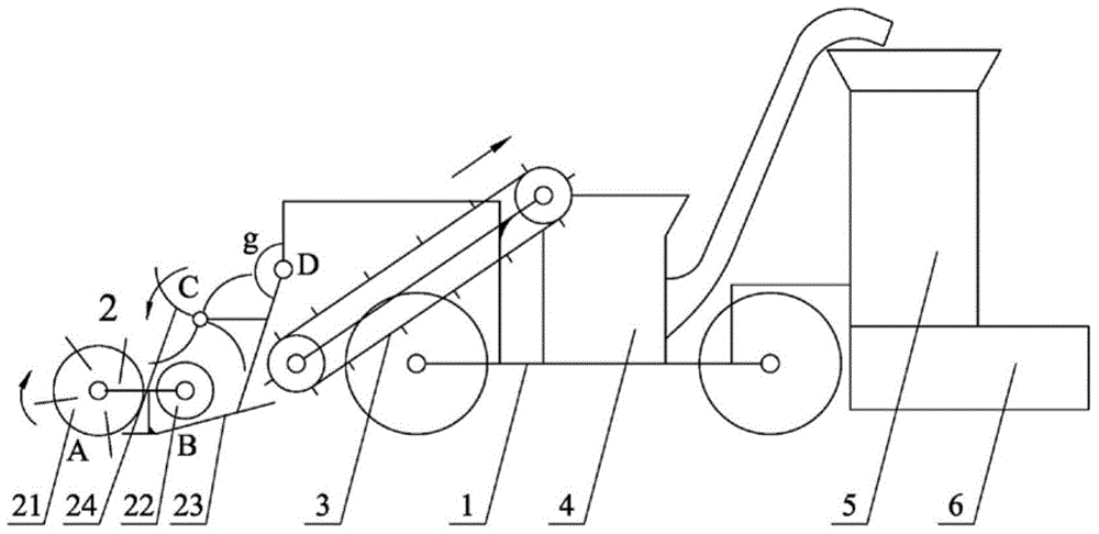
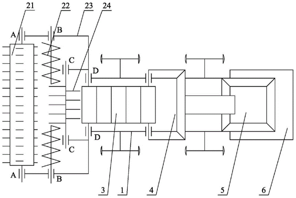
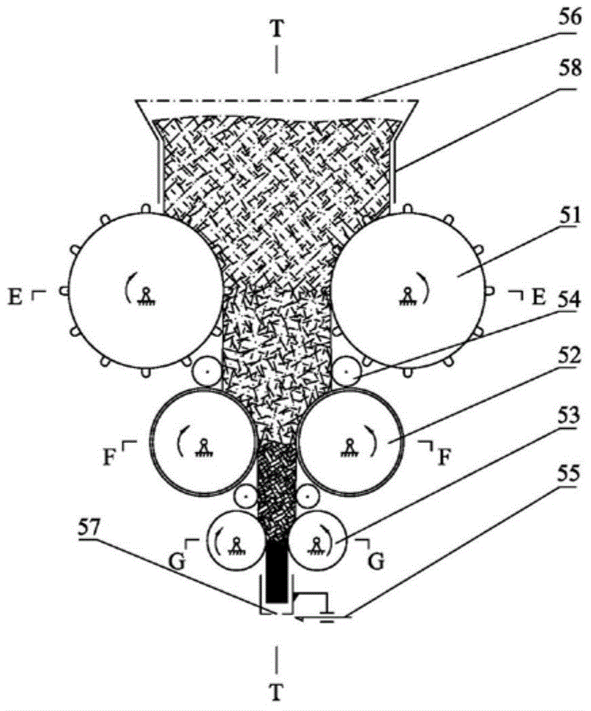
[0023] figure 1 The schematic diagram of the main view of the straw collection and briquetting vehicle is shown. The straw collection and briquetting vehicle includes: chassis 1, collection device 2, conveyor belt 3, hay cutter 4, multi-stage roller pressing straw forming device 5, and collecting hopper 6; The upper front end of the walking and wheeled chassis 1 is symmetrically provided with a collecting device 2, and the collecting device 2 and the vehicle frame of the chassis 1 are rotationally connected at point D in the vertical vertical plane of the vehicle, and the rotation axis DD (such as figure 2 shown), the posture of the collection device 2 is controlled and locked by the included angle g, and the middle part of the chassis 1 is provided with a conveyor belt 3, a hay cutter 4, and a multi-sta...


PUM


Abstract

The invention relates to the technical field of straw collection, pressing and bundling through agricultural machines, and discloses a straw collecting and briquetting vehicle which comprises a chassis, a collecting device, a conveyer belt, a hay cutter, a multistage roll straw forming device and a collecting hopper. During a working process of the vehicle, the collecting device picks up straws on the ground to a collecting bench, a material poking wheel conveys straws on the collecting bench to the conveyer belt, and the conveyer belt conveys straws into the hay cutter. The hay cutter chops straws in certain length and conveys the straws into the multistage roll straw forming device, straws in the multistage roll straw forming device are rolled into high-density straw bars by continuous multistage rolls, and the straw bars are cut by a cutter to form high-density straw blocks which fall onto the collecting hopper from a discharge hatch. The straw collecting and briquetting vehicle realizes continuous collection, conveying and multistage rolling, and is a self-propelled combined operation device which shape straw blocks with high-density and no bundling ropes. The high-density straw cubes can be used as agricultural building materials or fuel.

Description

technical field [0001] The invention relates to a straw collection and briquetting vehicle, which belongs to the technical field of agricultural machinery straw collection and baling. In particular, it relates to a self-propelled straw collection and briquetting vehicle for continuous collection, transportation and multi-stage roll forming. Background technique [0002] According to statistics, the annual output of crop straw in the world is more than 2.9 billion tons, while the annual straw amount in my country is about 700 million tons. Except for a part of the straw used for energy, feed, and fertilizer, there are still 1 / 3 of the straw that has not been utilized. . Some of these unused straws are disposed of by incineration, and a large amount of straw resources are wasted. Due to the characteristics of scattered distribution and loose structure of biomass straw resources in my country, there are problems such as large transportation volume, low storage density and high...

Claims


Application Information

Patent Timeline
IPC IPC(8): A01D89/00B30B11/18B30B15/30A01F29/00
Inventor 韩鲁佳姚媛李海涛刘平义魏文军张绍英
Owner CHINA AGRI UNIV
Learn More