
Current-to-voltage conversion circuit with input bias and active power filtering effects and current-to-voltage conversion method

A technology of current-voltage conversion and bias current source, which is applied in the direction of logic circuit connection/interface layout, etc., can solve the problems of unfavorable circuit cost control, miniaturization design, and large printed circuit board space, and achieve good application prospects and easy The effect of integration and simple circuit structure

Active Publication Date: 2015-07-29
NANJING PANENG TECHNOLOGY DEVELOPMENT CO LTD
View PDF6 Cites 4 Cited by
  • Summary
  • Abstract
  • Description
  • Claims
  • Application Information

AI Technical Summary

Problems solved by technology

[0004] The purpose of the present invention is to overcome the need for multi-chip operational amplifiers when the existing bipolar current signal is biased and converted into a unipolar signal, which occupies a large space on the printed circuit board, which is not conducive to the cost control and miniaturization of the circuit design needs

Method used


Image

  • Current-to-voltage conversion circuit with input bias and active power filtering effects and current-to-voltage conversion method
  • Current-to-voltage conversion circuit with input bias and active power filtering effects and current-to-voltage conversion method
  • Current-to-voltage conversion circuit with input bias and active power filtering effects and current-to-voltage conversion method

Examples


Embodiment Construction

[0024] The present invention will be further described below in conjunction with the accompanying drawings. The following examples are only used to illustrate the technical solution of the present invention more clearly, but not to limit the protection scope of the present invention.

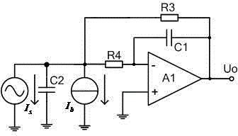
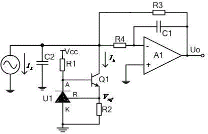
[0025] Such as figure 2 As shown, the current-voltage conversion circuit with input bias and active filtering of the present invention includes an operational amplifier A1 and a bias current source, and the current signal I s After being connected in parallel with the bias current source, it is connected to the inverting input terminal of the operational amplifier A1 through the resistor R4, the positive input terminal of the operational amplifier A1 is grounded, and the output terminal of the operational amplifier A1 is connected to its inverting input terminal through the capacitor C1, so The bias current source Ib is used to realize the current signal I to be converted s The DC bias of the...


PUM


Abstract

The invention discloses a current-to-voltage conversion circuit with input bias and active power filtering effects and a current-to-voltage conversion method. The current-to-voltage conversion circuit with the input bias and active power filtering effects comprises an operational amplifier A1 and a bias current source; after being in parallel connection with the bias current source, a current signal (Is) is connected to a reverse input end of the operational amplifier A1; a forward input end of the operational amplifier A1 is connected with the ground; an output end of the operational amplifier A1 is connected with a reverse input end of the operational amplifier A1 through a capacitor C1 and is connected to a parallel-connection node between the bias current source and the current signal (Is) through a negative feedback resistor R3; and the node is in parallel connection with a capacitor C2 in a grounding manner. Input bias is implemented through the current source, active power filtering and current-to-voltage conversion are implemented through the operational amplifier, the circuit is simple, the cost is low, and the application prospect is high.

Description

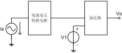
technical field [0001] The invention relates to a current-voltage conversion circuit and method with input bias and active filtering, and belongs to the technical field of electronic circuits. Background technique [0002] Because the current signal has a good anti-interference ability, many sensors in the industrial control field output current signals. However, due to the high cost performance of multi-channel unipolar ADCs, in order to meet the range requirements of unipolar ADCs, it is necessary in many occasions The bipolar current signal from the sensor is biased and converted into a unipolar signal, and low-pass filtering is required to meet the requirements of the sampling theorem. [0003] At present, the typical scheme is that the current signal output by the sensor I s First, the voltage conversion of the signal is completed through the current-voltage conversion circuit, and then the offset of the signal is completed through an adder, such as figure 1 As shown,...

Claims


Application Information

Patent Timeline
IPC IPC(8): H03K19/0175
Inventor 庞吉耀陈雷
Owner NANJING PANENG TECHNOLOGY DEVELOPMENT CO LTD
Learn More