
Super-quick vacuum switch device

A technology of vacuum switch and fast switch, which is applied in the direction of electric switch, high voltage/high current switch, high voltage air circuit breaker, etc. Problems such as large mass of the moving part, to achieve the effect of easy expansion, light moving mass, and simple structure

Inactive Publication Date: 2015-07-29
成都恒科瑞恩智能电气科技有限公司
View PDF10 Cites 8 Cited by
  • Summary
  • Abstract
  • Description
  • Claims
  • Application Information

AI Technical Summary

Problems solved by technology

In the prior art, the mechanical switches used for high-voltage DC circuit breakers mainly have the following problems: (1) Spring operating mechanisms, hydraulic operating mechanisms or permanent magnetic operating mechanisms are used, and the operating time of these traditional operating mechanisms is usually within several Ten ms, the response speed is slow; (2) The operating mechanism is placed at the ground potential, and the operating mechanism drives the contact of the arc extinguishing chamber to move through the insulating rod, and the mass of the moving part of the system is large; (3) Using single or double fractures, in order to meet After the fault is removed, the insulation withstand ability, the contact opening distance of the arc extinguishing chamber is tens of mm, and the contact movement time of the arc extinguishing chamber is long
Therefore, it is difficult for the mechanical switches of the prior art to meet the requirements of fast HVDC circuit breakers

Method used


Image

  • Super-quick vacuum switch device
  • Super-quick vacuum switch device
  • Super-quick vacuum switch device

Examples


Embodiment Construction

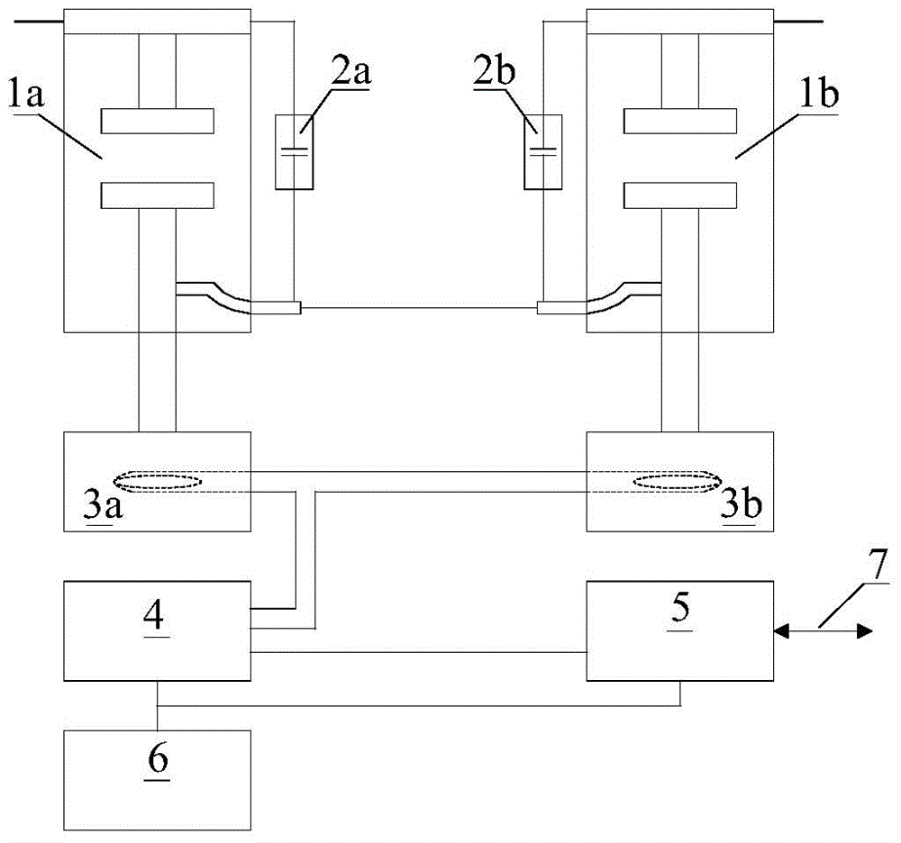
[0018] The specific embodiment of the present invention will be described with reference to the accompanying drawings. Such as figure 1 As shown, the ultra-fast vacuum switchgear includes two to four ultra-fast vacuum switch modules connected in series, including a first epoxy-sealed vacuum pole 1a and a second epoxy-sealed vacuum pole 1b, a first pressure equalizing device 2a and the second equalizing device 2b, the first operating mechanism 3a and the second operating mechanism 3b, the pulse current generator 4, the fast switch controller 5, the isolated auxiliary power supply 6 and the optical fiber 7;

[0019] The first operating mechanism 3a and the second operating mechanism 3b are respectively located under the first epoxy-embedded vacuum pole 1a and the second epoxy-embossed vacuum pole 1b, and are equipotentially connected; The first voltage equalizing device 2a and the second voltage equalizing device 2b are voltage equalizing circuits in which capacitors and resist...


PUM


Abstract

The invention relates to the field of high-voltage switches of power systems, in particular to a super-quick vacuum switch device. The super-quick vacuum switch device comprises two to four super-quick vacuum switch modules which are connected in series; a first operating mechanism and a second operating mechanism of each super-quick vacuum switch module are respectively positioned below a first epoxy embedded vacuum pole and a second epoxy embedded vacuum pole; a first voltage equalizing device and a second voltage equalizing device are respectively connected in parallel with the first epoxy embedded vacuum pole and the second epoxy embedded vacuum pole; a pulse current generator is connected with each of the first operating mechanism and a second operating mechanism; an isolation auxiliary power supply outputs a first direct-current voltage to provide power for a quick switch controller, and outputs a second direct-current voltage to provide charging voltage for the pulse current generator; the quick switch controller is connected with the pulse current generator; the quick switch controller is communicated with a direct-current circuit breaker control device positioned at ground potential through an optical fiber. The switch device is light in moving mass, quick in response and simple in structure, and facilitates module cascade extension.

Description

technical field [0001] The invention relates to the field of high-voltage switches in electric power systems, in particular to an ultra-fast vacuum switch device. Background technique [0002] With the global energy shortage and environmental pollution becoming more and more serious, the utilization and development of renewable energy has been paid attention to by countries all over the world, especially the proportion of wind power in future energy supply will gradually increase. However, due to the intermittence and uncertainty of wind power output and the absorptive capacity of the power system, the effective utilization rate of wind power is not high. The multi-terminal direct current transmission system and direct current grid technology based on conventional direct current and flexible direct current are one of the effective technical solutions to solve the problem of grid connection and accommodation of new energy. [0003] However, due to the small impedance of the ...

Claims


Application Information

Patent Timeline
IPC IPC(8): H01H33/666H01H33/52
CPCH01H33/6662H01H33/52H01H33/666
Inventor 方春恩余建华李伟李涛任晓
Owner 成都恒科瑞恩智能电气科技有限公司
Learn More