Mode locking free oil cylinder hydraulic mode-locking plastic jetting-moulding machine

The technology of clamping cylinder and hydraulic lock is applied in the field of hydraulic clamping device without clamping cylinder. The effect of uniform distribution of force and compact structure of the whole machine

Inactive Publication Date: 2007-05-30
林谊
View PDF0 Cites 5 Cited by
  • Summary
  • Abstract
  • Description
  • Claims
  • Application Information

AI Technical Summary

Problems solved by technology

Whether it is single-cylinder or multi-cylinder mold clamping, the disadvantage is that the use of clamping cylinders requires extremely high sealing conditions, and mold clamping is prone to oil leakage and pressure relief, resulting in insufficient clamping force, so the processing of parts is difficult and costly. , assembly and maintenance are difficult, and the greater the clamping force, the greater the radius of the required clamping cylinder, the more difficult the sealing, the more difficult the control of the oil circuit, and the more hydraulic oil used, plus the oil cylinder itself. The greater the mass, the greater the movement quality, and the greater the power required for frequent mold opening and closing movements, so it is difficult to apply to large-tonnage injection molding machines. At the same time, the maximum stroke of the movable platen can only reach the length of the clamping cylinder, and the longer the stroke , the longer the clamping cylinder, the greater the movement quality. The frequent reciprocating movement of the hydraulic oil during the mold opening and closing process affects the running speed, and it is easy to increase the oil temperature and accelerate the aging of the sealing ring, and a large amount of hydraulic oil is discarded when the machine is scrapped. will cause serious environmental pollution
[0004] The common disadvantages of toggle lever clamping and hydraulic clamping are: complex structure, requiring high-precision parts and high-precision cooperation, many consumables, difficult manufacturing, high cost, high energy consumption, difficult maintenance, large environmental pollution, and clamping The force closing line is long, the system rigidity is poor, the mold opening and closing stroke is limited, and it takes up a lot of space, etc.

Method used


Image

  • Mode locking free oil cylinder hydraulic mode-locking plastic jetting-moulding machine
  • Mode locking free oil cylinder hydraulic mode-locking plastic jetting-moulding machine
  • Mode locking free oil cylinder hydraulic mode-locking plastic jetting-moulding machine

Examples


Embodiment Construction

[0026] The present invention will be described in detail below in conjunction with the accompanying drawings.

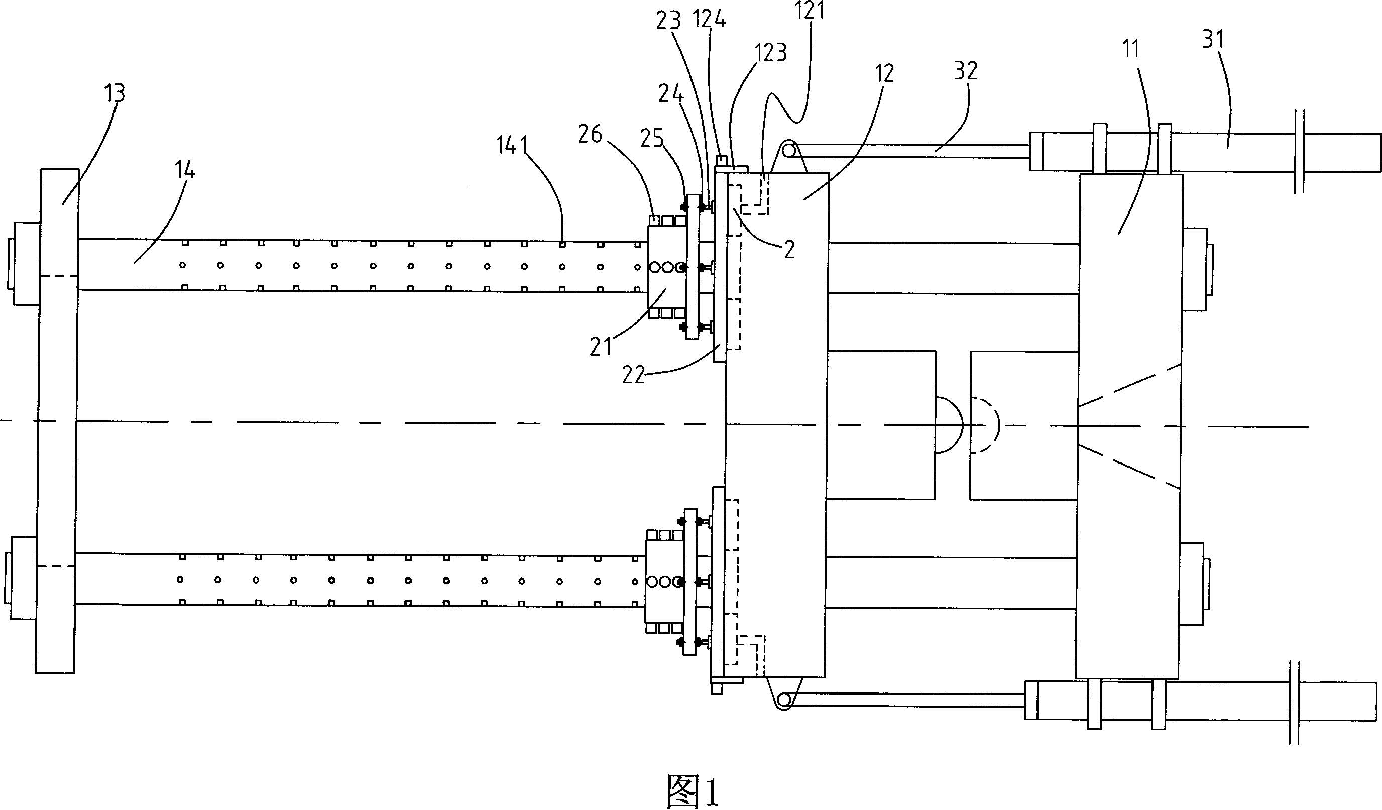
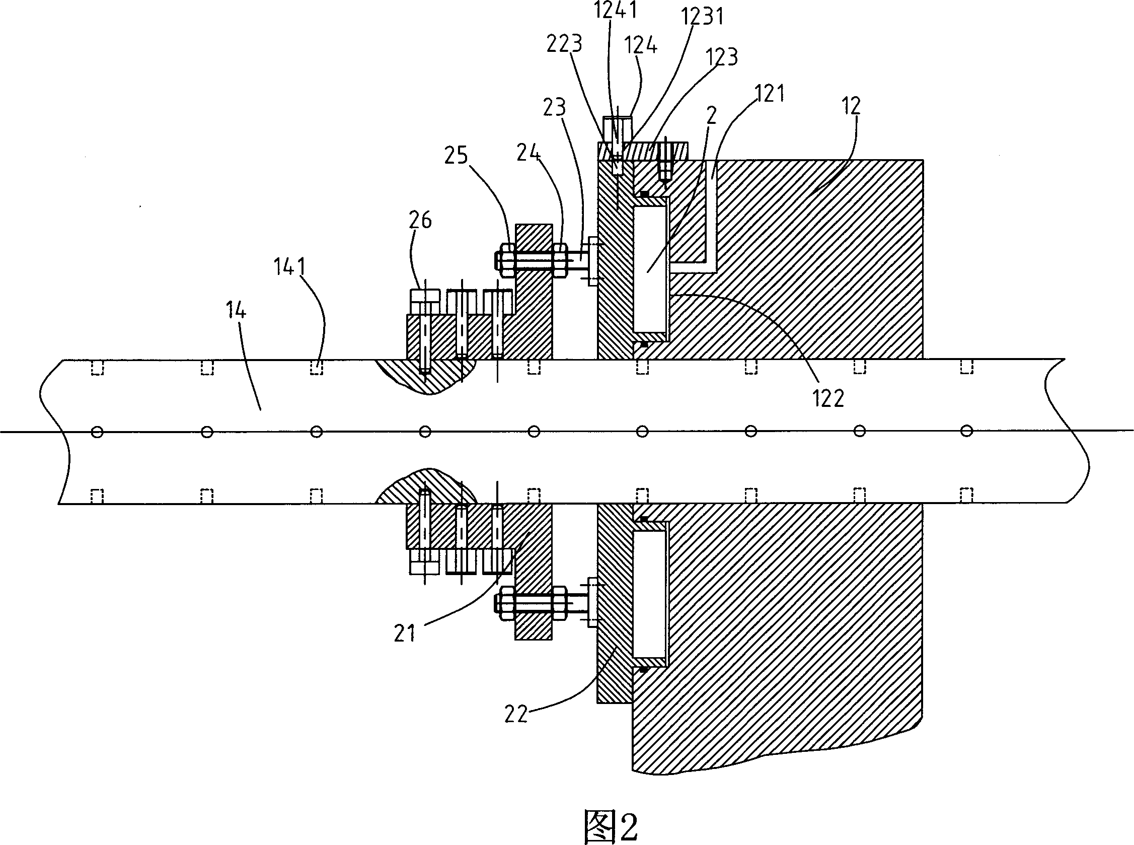
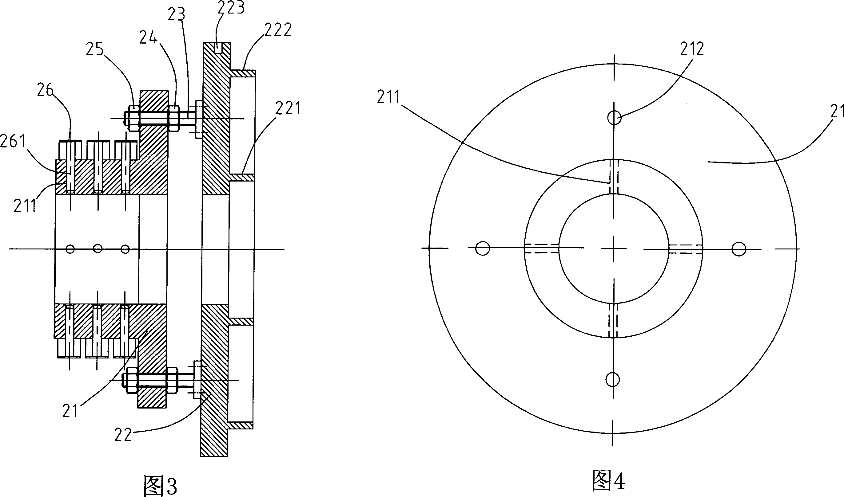
[0027] As shown in Figures 1 to 8, it is a hydraulic clamping injection molding machine without a clamping cylinder, which includes a fixed platen 11, a movable platen 12, and a rear platen 13, which pass through the two ends of the movable platen to connect with the fixed platen and the rear platen respectively. The fixed tie rod 14, the free positioning mold locking group composed of the stepped sleeve 21 and the end cover 22, and the quick mold moving cylinder 41. The pull rod 14 is provided with more than one row of radially symmetrically distributed first pin holes 141 distributed along the axial direction; On the pull rod 14, the stepped sleeve and the end cover are tightly connected by bolts 23 and two nuts 24, 25. One end of the bolt is fixed on the end cover 22 and the other end passes through the through hole opened at the base of the stepped sleeve and is ...


PUM


Abstract

The locking mold oil tank free hydraulic locking mode injection machine comprises a static mold plate, an active mold plate, cross rod fastened to both ends of the static mold and back mold plate, quick mold displacing oil tank on the static mold plate whose sticking end connected with the active mold plate. It also comprises stepwise sleeves and end cap, No.1 pin hole, with the stepwise sleeve and end cap fastened by bolt and two nuts into free positioning locking mold set, more than one No.1 electromagnetic pins on the circumference of the stepwise sleeve composed of pin inserting to the No.1 pin hole and the coil driving the up and down movement of the pin, No.2 pin hole and two ring boss at one side, sealing tightly with grooves surrounding the cross rod, forming four compression cavity by four end caps and active mold plates, inside the active mold plate having oil through hole connecting the compression cavity with the hydraulic source, sticking plate on the active mold plate with No.2 electromagnetic pin and through holes, with the No.2 electromagnetic pin being able to pass the through hole, sticking to the pin inside the No.2 pin hole and driving the up and down movement of the coil on the pin . Free from locking mold oil tank, with increased locking mold force, it solves the sealing issue of the locking mold oil tank, with small components, low requirements for the parts, small consumption materials and moving weight, long opening stroke of the active mold plate, and strong suitability for the mold.

Description

technical field [0001] The invention relates to a hydraulic mold clamping injection molding machine without a mold clamping oil cylinder, in particular to a hydraulic mold clamping device without a mold clamping oil cylinder. technical background [0002] At present, the injection molding machines used at home and abroad are generally in the toggle lock mode, the hydraulic lock mode and the newly emerging ball screw plus toggle composite lock mode. Elastic deformation force is used to clamp the mold. Due to the many hinged toggles and hinge points, the force length cannot be guaranteed to be equal during manufacturing and assembly. At the same time, a large amount of lubricating oil and a complicated lubrication system are required. Long running time will easily lead to wear and cause structural imbalance. The gap between the lengths of the toggle levers on both sides increases, and wear is accelerated, forming a vicious circle, which leads to crawling phenomenon in the open...

Claims


Application Information

Patent Timeline
Patent Type & Authority Applications(China)
IPC IPC(8): B29C45/67B29C45/64
Inventor 林谊
Owner 林谊
Why Eureka
Try Eureka