A rebound rebound instrument with an auxiliary measuring device

A technology of auxiliary measurement and auxiliary device, which is applied in the direction of testing material hardness, etc., can solve the problems of reducing the durability and measurement accuracy of the instrument, affecting the adjustment of the impact plane and the hammer body, and the slow measurement speed of the rebound instrument, so as to save physical strength, The effect of increasing friction and making it easier to exert force

Active Publication Date: 2018-03-13
CHINA POWER CONSRTUCTION GRP GUIYANG SURVEY & DESIGN INST CO LTD
View PDF5 Cites 0 Cited by
  • Summary
  • Abstract
  • Description
  • Claims
  • Application Information

AI Technical Summary

Problems solved by technology

But every time you measure, you first need to push the hammer body to a certain position by external force, and then use the control button to release the elastic force accumulated in the compression spring to push the hammer body out, so that the hammer body bounces vertically on the concrete surface, while the traditional rebound When measuring, it is only necessary to push the rebound hammer at a constant speed until the bullet hammer completely enters the interior of the rebound hammer to complete a measurement. Therefore, the measurement speed of the rebound hammer is slow, which is a waste of time. In the process of positioning, the flat hat head is a force transmission structure, so after long-term use, there will inevitably be a certain deformation, which will affect the effect of adjusting the verticality between the impact plane and the hammer body
In addition, during the retraction and ejection process of the hammer body of this invention, there will be a cavity at the front end of the device, which will allow external dust, water, etc. to enter the interior of the instrument, which will reduce the durability and measurement accuracy of the instrument.

Method used


Image

  • A rebound rebound instrument with an auxiliary measuring device
  • A rebound rebound instrument with an auxiliary measuring device
  • A rebound rebound instrument with an auxiliary measuring device

Examples


Embodiment Construction

[0031] The technical solution of the present invention is further described below in conjunction with the accompanying drawings, but the scope of protection is not limited to the description.

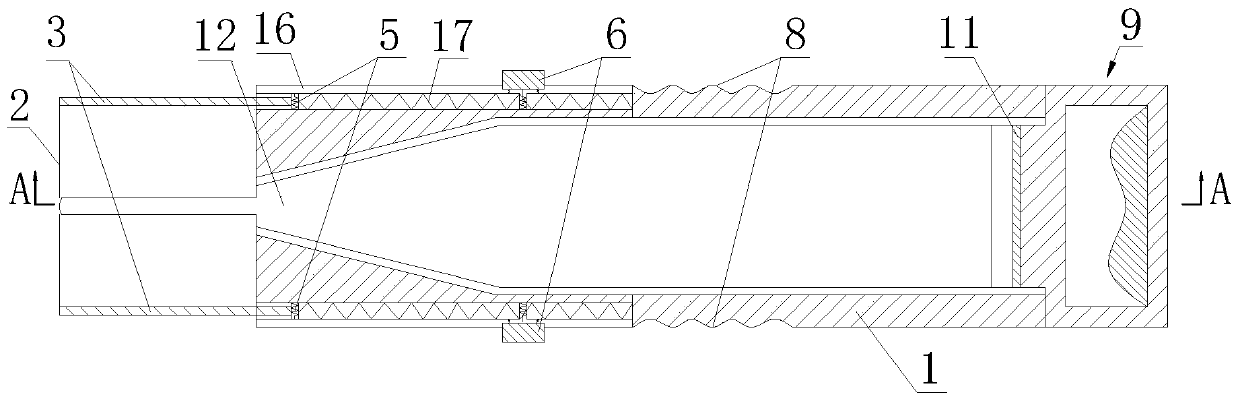
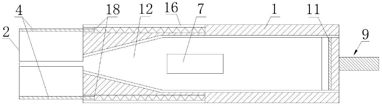
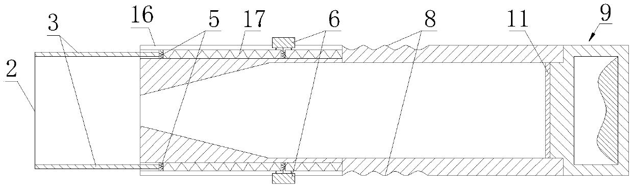
[0032] like Figure 1 to Figure 9 As shown, a rebound hammer with an auxiliary measuring device according to the present invention includes a rebound hammer main body 12 and an auxiliary device set outside the rebound hammer main body 12, and the auxiliary device consists of a circular casing 1 and a set The conduit 16 on the upper part of the circular casing 1 is composed of a circular flat plate 2 arranged at the top of the circular casing 1, and a positioning mechanism and a guiding mechanism connected with the circular flat plate 2 are respectively arranged in the conduit 16. The positioning mechanism includes two telescopic positioning rods 3 symmetrically arranged on the circular flat plate 2, and the ends of the two telescopic positioning rods 3 far away from the circular flat pl...


PUM


Abstract

The invention discloses a rebound hammer with an auxiliary measuring device, which comprises a rebound hammer main body and an auxiliary device set outside the rebound hammer main body. Consisting of a conduit, the top of the circular casing is provided with a circular plate, and a positioning mechanism and a guiding mechanism connected with the circular plate are respectively provided in the conduit, and the positioning mechanism includes two symmetrically arranged on the circular plate. Telescopic positioning rods, one end of the two telescopic positioning rods away from the circular flat plate is connected with a spring buckle, and the rear end of the spring buckle is connected with a spring B; the guide mechanism includes two symmetrically arranged on the circular flat plate Telescopic guide rods, one end of the two telescopic guide rods away from the circular flat plate is connected with a backing plate, and the rear ends of the backing plates are connected with spring B. The invention can make the axis of the rebound hammer always perpendicular to the concrete test surface, greatly reducing the working intensity of workers and improving the rebound working efficiency.

Description

technical field [0001] The invention belongs to the technical field of concrete structure detection, in particular to a rebound hammer with an auxiliary measuring device, which is mainly used for measuring the strength of concrete. Background technique [0002] The concrete rebound tester uses a spring to drive the bounce hammer and the restoring force of the instantaneous elastic deformation generated by the bounce rod hitting the concrete surface, so that the bounce hammer drives the pointer to bounce back and indicates the distance of the bounce, so as to rebound The value is used as one of the indicators related to the compressive strength of concrete, and then combined with the carbonation depth of concrete in the corresponding area, the compressive strength of concrete can be deduced. Because the rebound tester has the advantages of lightness, flexibility, low price, no power supply, easy to grasp, the button is not easy to fall off by stretching process, and the point...

Claims


Application Information

Patent Timeline
Patent Type & Authority Patents(China)
IPC IPC(8): G01N3/48
Inventor 彭浩江志红徐卫平邓华常强张秋实
Owner CHINA POWER CONSRTUCTION GRP GUIYANG SURVEY & DESIGN INST CO LTD
Why Eureka
Try Eureka