
Automatic scriber and method of application thereof

An automatic scribing and scribing technology, applied in workshop equipment, manufacturing tools, etc., can solve the problems of inconsistent scribing depth, high manual scribing work intensity, and inability to maintain constant scribing, etc., so as to improve the scribing efficiency. , the effect of reducing the scribing intensity, reducing the intensity

Active Publication Date: 2016-06-22
API ZC PRECISION INSTUMENT CO LTD
View PDF5 Cites 1 Cited by
  • Summary
  • Abstract
  • Description
  • Claims
  • Application Information

AI Technical Summary

Problems solved by technology

Manual scribing is intensive and inefficient, especially for large mechanical blanks.
In the prior art, it is impossible to provide an axial compensation force for the scribing device, and the axial pressure exerted by the scribing on the surface of the workpiece is an unsteady force, which makes the scribing needle draw lines with different depths on the surface of the workpiece, for example, Generally, the surface of the part to be marked is an uneven surface, and there are many grooves and protrusions on the surface. When the existing stylus travels on the surface of the part to be marked, the stroke of the stylus will not change. Therefore, this The scribing needle will draw a deeper line when passing the raised area, and when passing the groove area, it will cause no scribing in the groove. In the prior art, there is another type of scribing device. This type of scribing device The device uses a spring device, and its structure is as follows: a sleeve, a spring is arranged in the sleeve, one end of the spring is connected to the right end of the sleeve, and the other end of the spring is connected to the needle, when the needle passes through the raised area, the spring is compressed , the stroke of the stylus becomes smaller, when the stylus passes through the groove area, the spring is stretched, and the stroke of the stylus becomes larger. Although this type of device can reduce the depth of the scribing on the raised surface to a certain extent, or can be used in The groove area forms a scribe line, but the overall scribe line still cannot maintain a constant axis pressure, so its scribe depth is still not consistent

Method used


Image

  • Automatic scriber and method of application thereof
  • Automatic scriber and method of application thereof
  • Automatic scriber and method of application thereof

Examples


Embodiment 1

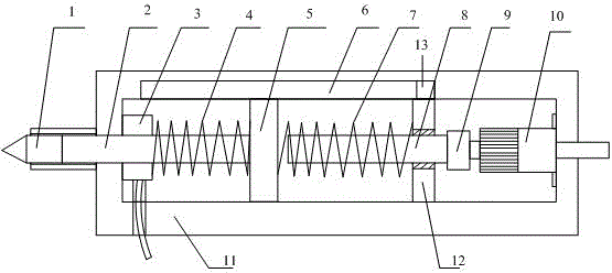
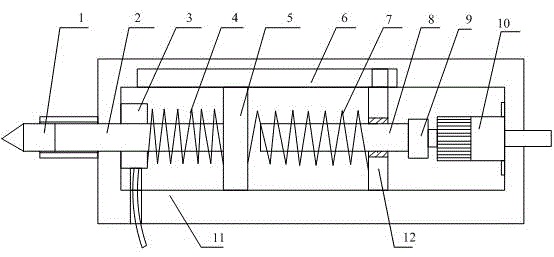
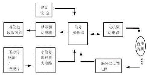
[0030] The automatic scriber includes a hollow stylus cylinder 11, a pressure detection device 3 is installed on the inner wall of the left end of the stylus cylinder 11, a DC motor 10 is installed on the inner wall of the right end of the stylus cylinder 11, and a scribing needle 1 is installed on the left end. The needle linkage shaft 2, the right end of the needle linkage shaft 2 is inserted into the needle cylinder 11 from the outer wall of the left end of the needle cylinder 11, the needle linkage shaft 2 runs through the pressure detection device 3 at the same time, and the needle linkage shaft 2 extends to the needle cylinder One end inside 11 is connected with a slide block 5, and a first pre-tightened coil spring 4 sleeved on the needle linkage shaft 2 is set between the slide block and the pressure detection device 3, and one end of the first pre-tightened coil spring is connected to the pressure detection device 3. The device 3 is connected, and the other end of the ...


PUM


Abstract

The invention discloses an automatic scriber and an application method thereof. The automatic scriber comprises a scribing pin cylinder, wherein a pressure detection device is arranged on the inner wall at the left end of the scribing pin cylinder, and a direct-current motor is arranged on the inner wall at the right end of the scribing pin cylinder; the automatic scriber further comprises a scribing pin linkage shaft with a scribing pin arranged at the left end, the right end of the scribing pin linkage shaft is inserted into the scribing pin cylinder from the outer wall at the left end of the scribing pin cylinder and simultaneously penetrates through the pressure detection device, one end of the scribing pin linkage shaft extending into the scribing pin cylinder is connected with a sliding block, and a first preloaded spiral spring sleeved on the scribing pin linkage shaft is arranged between the sliding block and the pressure detection device; the automatic scriber also comprises a lead screw shaft arranged in the scribing pin cylinder, a lead screw nut is arranged on a jacket of the lead screw shaft, the right end of the lead screw shaft is connected with a rotary output shaft of the direct-current motor through a coupler, a second spiral spring is arranged between the lead screw nut and the sliding block, one end of the second spiral spring is connected with the sliding block, the other end of the second spiral spring is connected with the lead screw nut, and the second spiral spring sleeves on the external diameter of the lead screw shaft.

Description

technical field [0001] The invention relates to the field of scribing, in particular to an automatic scribing device with an automatic compensation function, which can make the axial pressure of the scribing on the surface of the workpiece a constant force, and the force can make the scribing needle draw a uniform line on the surface of the workpiece. Background technique [0002] At present, both at home and abroad, manual marking is still used to mark mechanical blanks. The marking tools are nothing more than marking needles, planning, powder lines, etc. Marking needles are used for small areas, and powder lines are used for large strokes. , There is no good solution for the automated line process so far. Manual scribing is intensive and inefficient, especially for large mechanical blanks. In the prior art, it is impossible to provide an axial compensation force for the scribing device, and the axial pressure exerted by the scribing on the surface of the workpiece is an u...

Claims


Application Information

Patent Timeline
Patent Type & Authority Patents(China)
IPC IPC(8): B25H7/04
CPCB25H7/04B25H7/045
Inventor 刘锦潮
Owner API ZC PRECISION INSTUMENT CO LTD
Learn More