


Quick Research
Generate reliable direction feasibility study reports for your R&D in just a few steps.

Technical Q&A
Discover and master advanced knowledge NOW. Basics, ideas, possibilities, all at once.

Find Solutions
As an expert in R&D theories, this can generate solutions to your technical problems instantly.

Evaluate Feasibility
Analyze your overall solution with one click, know your potential R&D risks in advance.

Monitor Landscape
Get weekly tech updates, stay abreast of the latest tech innovations and key insights.
Trimmer
An edge trimming machine and edge trimming technology, applied in the direction of hand-held lawn trimmers, etc., can solve problems such as damage, bumping of cutting elements, etc.
- Summary
- Abstract
- Description
- Claims
- Application Information
AI Technical Summary
Problems solved by technology
Method used
Image

Examples
Embodiment approach 1
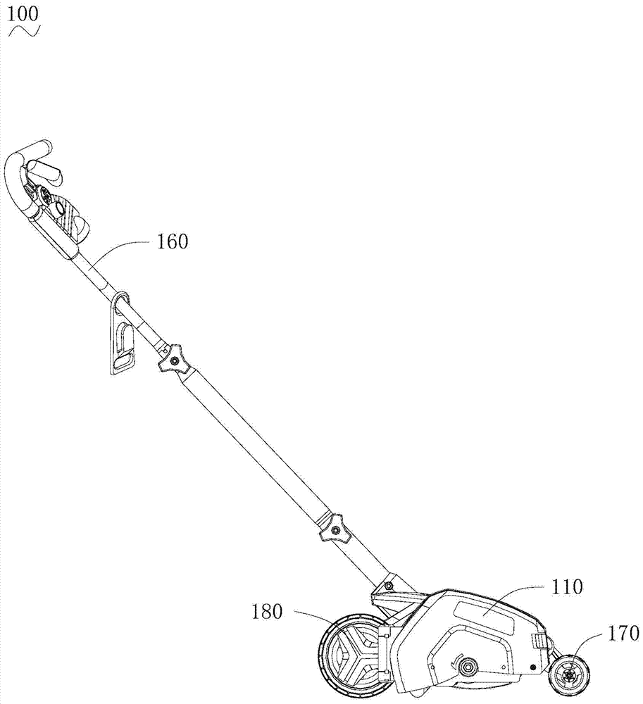
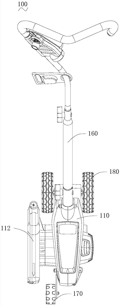
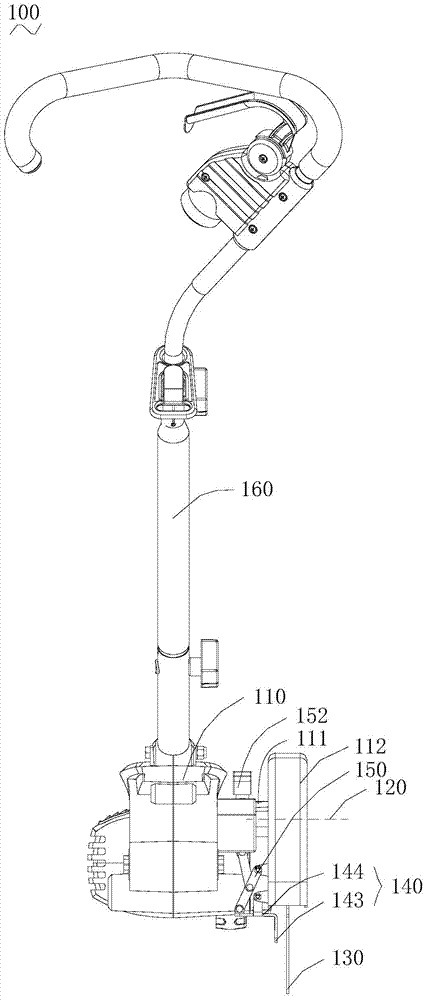
[0046] Please refer to Figure 1 to Figure 4 , this embodiment discloses a trimming machine 100, the trimming machine 100 includes a housing 110, an output shaft 120 extending out of the housing 110, a cutting element 130 mounted on the output shaft 120, and a guide mechanism partially arranged on the housing 110 150 , the guide mechanism 150 includes a trimming guide plate 140 for protecting the cutting element and a position adjustment mechanism for rotatably connecting the trimming guide plate 140 with the housing 110 . The position adjustment mechanism includes a lever 151 that can slide up and down along the casing 110 and a connecting assembly that can be driven by the lever 151 and connected with the trimming guide plate 140. Transitions between an open position and a stowed position away from the cutting element 130 . Wherein, the cutting element 130 is a cutting wire or a cutting tool.
[0047] The trimming guide plate 140 has a baffle portion 143 capable of protect...
Embodiment approach 2
[0053] The difference from Embodiment 1 lies in the specific structure of the guide mechanism.
[0054] Please refer to Figure 10 , as an extended implementation of Embodiment 1, a connecting piece 242 is fixed in the middle of the trimming guide plate 240, and the guide mechanism 250 includes a first node 253 fixed on the housing 110 and a first node 253 that is rotatably connected to one end of the trimming guide plate 240. Two connecting pieces 255 . Wherein, the first node 253 is rotatably connected to the connecting member 242 , and the second connecting member 255 is rotatably connected to one end of the lever 251 . The combined connecting structure of the first node 253 and the second connecting member 255 constitutes a connecting component of the guiding mechanism 250 . When the lever 251 is lifted upward, it drives the second connecting member 255 to move upward. At this time, the second connecting piece 255 drives one end of the trimming guide plate 240 to lift, ...
Embodiment approach 3
[0056] The difference from Embodiments 1 and 2 is that the guiding mechanism 350 is a four-bar mechanism.
[0057] Please refer to Figure 11 and Figure 12 , the guide mechanism 350 includes a first node 353 fixed on the housing 110, a third node 356, a first connecting piece 354 rotatably connected to the first node 353, and a third connecting piece rotatably connected to the third node 356 357 , the second connecting piece 355 rotatably connected to one end of the trimming guide plate 340 and the fourth connecting piece 358 rotatably connected to one end of the lever 351 . Wherein, the second connecting member 355 , the third connecting member 357 and the fourth connecting member 358 are rotationally connected. A second node 341 that can be rotatably connected to the first connecting member 354 is disposed in the middle of the trimming guide plate 340 . The combined connection structure of the first node 353 , the third node 356 , the first connecting member 354 , the se...
PUM
 Abstract
Description
Claims
Application Information
 - R&D Engineer
- R&D Manager
- IP Professional
- Industry Leading Data Capabilities
- Powerful AI technology
- Patent DNA Extraction
Browse by: Latest US Patents, China's latest patents, Technical Efficacy Thesaurus, Application Domain, Technology Topic, Popular Technical Reports.
© 2024 PatSnap. All rights reserved.Legal|Privacy policy|Modern Slavery Act Transparency Statement|Sitemap|About US| Contact US: help@patsnap.com