
Rotary switch

A technology of a rotary switch and an external rotary shaft, which is applied in the field of rotary switches, can solve the problems such as the removal of the abutment member 4 of the turntable and then embedding into another groove, the insufficient number of switching segments, and the inability to make precise electrical contact.

Inactive Publication Date: 2017-01-11
SOLTEAM ELECTRONICS DONG GUAN +2
View PDF6 Cites 0 Cited by
  • Summary
  • Abstract
  • Description
  • Claims
  • Application Information

AI Technical Summary

Problems solved by technology

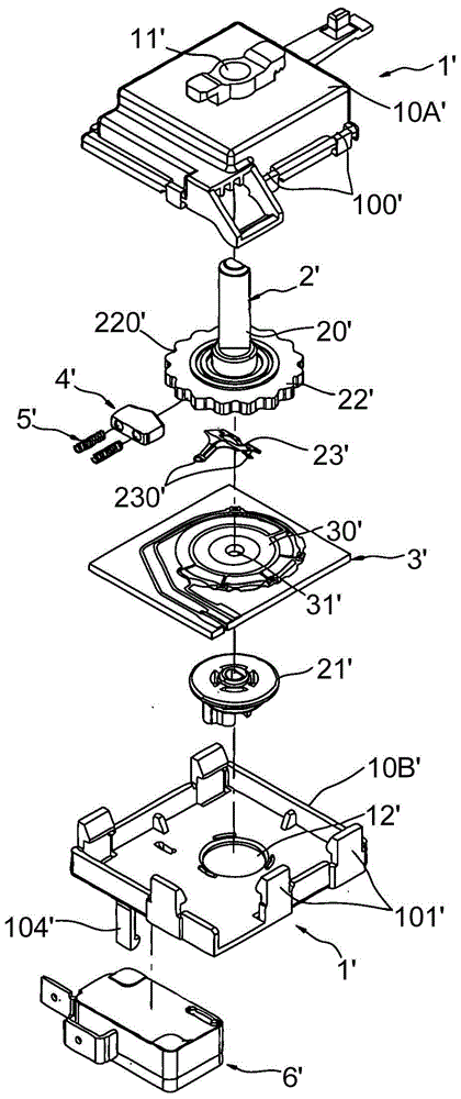
Since the rotary switch 1' adopts a single-axis and one-way rotation design, the number of switching segments can reach up to 16 segments; however, for specific electrical products, the number of switching segments of 16 segments is still not enough
[0008] 2. The conductive bumps 230' of the conductive sheet 23' cannot be precisely electrically contacted with the corresponding two electrical connection areas 30'
When switching the number of stages of the rotary switch 1', turn the rotary body 20' at an angle (for example, 20°) so that the top of the turntable abutting member 4' moves out of the groove 220' and then fits into another groove 220' However, since the turntable abutment 4' is embedded in the groove 220' based on the force of the two springs 5', once the two springs 5' provide uneven forces, the turntable abutment 4' cannot be completely Move out from the groove 220' and then insert into another groove 220'; at this time, the conductive bumps 230' of the conductive sheet 23' cannot be electrically contacted with the corresponding two electrical connection areas 30' precisely, and thus It will affect the smooth function switching of electrical products

Method used


Image

  • Rotary switch
  • Rotary switch
  • Rotary switch

Examples


Embodiment Construction

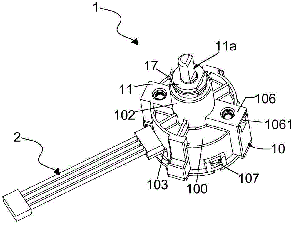
[0072] In order to describe the rotary switch provided by the embodiment of the present invention more clearly, the preferred embodiments of the present invention will be described in detail below with reference to the drawings.

[0073] see image 3 and Figure 4 , image 3 and Figure 4 shows a perspective view of a rotary switch provided by an embodiment of the present invention; and, please also refer to Figure 5 and Image 6 , Figure 5 and Image 6 An exploded view of the rotary switch provided by the embodiment of the present invention is shown. As shown in the figure, the rotary switch 1 provided by the embodiment of the present invention includes: a main cover body 10, a bottom cover plate 16, a hollow outer rotating shaft 11, a first turntable 12, a first propping member 13, a first metal dome 14, The inner rotating shaft 11a, the second turntable 12a, the second abutment piece 13a, the second metal dome 14a, and the double-sided circuit board 15. Wherein, a...


PUM


Abstract

The invention discloses a rotary switch in a double-shaft (optional) bidirectionally-rotatable design, up to 32 switching segments. In addition, an abutting member provided with a spring cavity is provided and used to hold and confine a compression spring therein, thus when stressed and compressed, the compression spring is avoided being bent, and the abutting member can be completely embedded in a cavity of a turnplate; smooth function switching is ensured for electric products.

Description

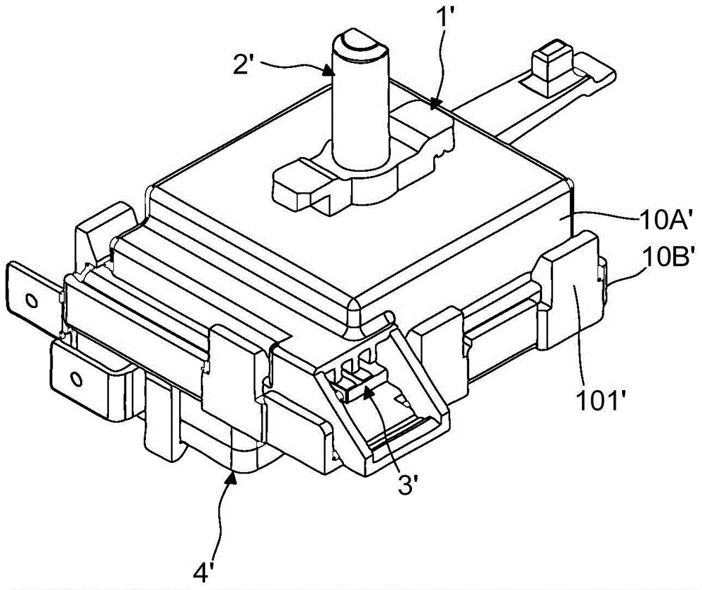
technical field [0001] The invention relates to the related field of switch components, in particular to a rotary switch. Background technique [0002] Rotary switches are often used in electrical products, especially in electrical products that require segment switching, such as electric fans, lamps, washing machines, etc. Therefore, the rotary switch usually includes the switching of multiple functional segments, so the user can achieve the purpose of switching and switching between the functional segments as long as the adjustment knob of the rotary switch is driven. [0003] see figure 1 and figure 2 , figure 1 and figure 2 An exploded view and a perspective view of a rotary switch in the prior art provided by an embodiment of the present invention are respectively shown. like figure 1 and figure 2 As shown, the prior art rotary switch 1' has a multi-stage switching function, and includes: a cover body 10A', a base 10B', a rotating unit 2', a base plate 3', a t...

Claims


Application Information

Patent Timeline
Patent Type & Authority Patents(China)
IPC IPC(8): H01H19/54H01H19/08H01H19/10
CPCH01H19/08H01H19/10H01H19/54
Inventor 何应松陈建满彭志明陈志威
Owner SOLTEAM ELECTRONICS DONG GUAN
Learn More