
Method for calculating stress distribution of composite interference fit connector

A technology of interference fit and calculation method, which is applied in calculation, special data processing applications, instruments, etc., and can solve problems such as large calculation time cost and increased calculation time

Active Publication Date: 2015-07-22
NORTHWESTERN POLYTECHNICAL UNIV
View PDF2 Cites 20 Cited by
  • Summary
  • Abstract
  • Description
  • Claims
  • Application Information

AI Technical Summary

Problems solved by technology

For the research on the residual stress of the hole edge of the interference fit joint of the composite material structure, the finite element simulation and numerical calculation method are mainly used (Kim S, He B, Shim C, and Kim D, "An experimental and numerical study on the interference-fit pin installation process for cross-ply glass fiber reinforced plastics (GFRP), Composites: Part B, vol.54, pp.153-162), the calculation time cost is very large, and the calculation time increases exponentially with the increase of calculation accuracy

Method used


Image

  • Method for calculating stress distribution of composite interference fit connector
  • Method for calculating stress distribution of composite interference fit connector
  • Method for calculating stress distribution of composite interference fit connector

Examples


Embodiment Construction

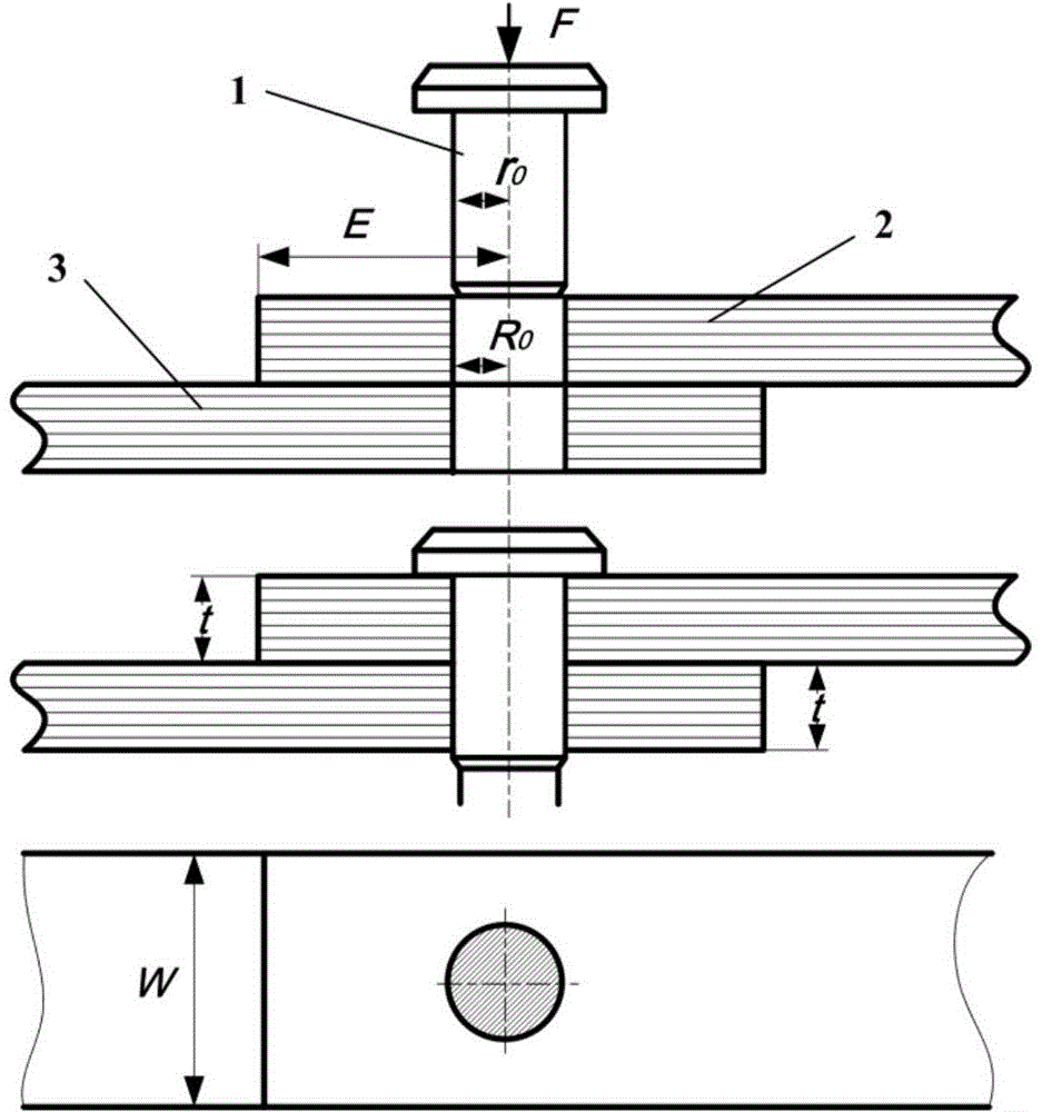
[0045] The main parts that the inventive method relates to are bolt (1), composite material plate (2,3), and wherein bolt initial radius is r 0 , The initial radius of the bolt hole of the composite plate is R 0 , the thickness of the composite material plate is t, the width of the composite material is W, and the shortest distance between the bolt hole and the end of the composite material plate is E. For interference fit connections, bolts are installed into composite bolt holes by cold extrusion.

[0046] The concrete steps of this method are as follows:

[0047] (1) Modeling of bolt complex stress function

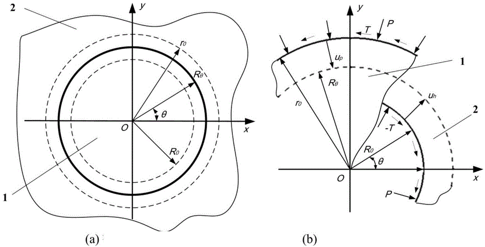
[0048] Before the bolt interference fit deformation, the cross section of the bolt is circular, and its initial radius is r 0 , let it be a simply connected region S p , the boundary circle is L p . When the normal contact stress P and tangential contact stress T act on the bolt boundary L p , its complex stress function can be expressed as:

[0049] ...


PUM


Abstract

The invention relates to a method for calculating stress distribution of a composite component interference fit connector hole edge. On the basis of the elastic mechanics complex potential theories of Muskhelishvili and Lekhnitskii, a nail stress distribution model and a hole stress distribution model are set up respectively; by analyzing the contact relationship of bolt-hole before and after deformation, bolt-hole contact stress is determined and substituted into a hole edge stress distribution model, precise calculation of a composite structure interference fit connector hole edge residual stress field is achieved, and the foundation is laid for structure connection design and strength analysis.

Description

technical field [0001] The invention belongs to the field of composite material structure processing and assembly, and in particular relates to a method for calculating the stress distribution at the edge of a hole in an interference fit joint of a composite material component, which is used for accurately calculating and analyzing the residual stress distribution at the edge of a hole after the interference fit connection of the composite material component. Background technique [0002] Compared with traditional metal materials, composite material structures have higher specific strength, specific stiffness, and good corrosion resistance. They are more and more widely used in structural weight-sensitive fields such as automobiles, aviation, and aerospace, especially carbon fiber. Reinforced composite materials (CFRP) have become an important material for modern aircraft structures. The main load-bearing structure of composite materials generally adopts mechanical connectio...

Claims


Application Information

Patent Timeline
Patent Type & Authority Applications(China)
IPC IPC(8): G06F17/50
Inventor 程晖宋丹龙刘平张开富
Owner NORTHWESTERN POLYTECHNICAL UNIV
Learn More