Heat transfer frame type LED light

A technology of LED lights and LED light sources, applied in lighting and heating equipment, cooling/heating devices of lighting devices, lighting devices, etc. Eliminate other problems to achieve the effect of increased heat transfer area and good heat dissipation effect

Inactive Publication Date: 2015-07-22
LEEDARSON IOT TECH INC
View PDF5 Cites 1 Cited by
  • Summary
  • Abstract
  • Description
  • Claims
  • Application Information

AI Technical Summary

Problems solved by technology

[0004] However, since the lamp body structure is not equipped with a heat transfer frame that guides the heat generated by the LED light source board to the heat sink, the heat generated by the LED light source board cannot be dissipated in time, and the heat dissipation effect is not good.

Method used


Image

  • Heat transfer frame type LED light
  • Heat transfer frame type LED light

Examples


Embodiment Construction

[0014] The present invention will be further described in detail below in conjunction with the accompanying drawings and specific embodiments.

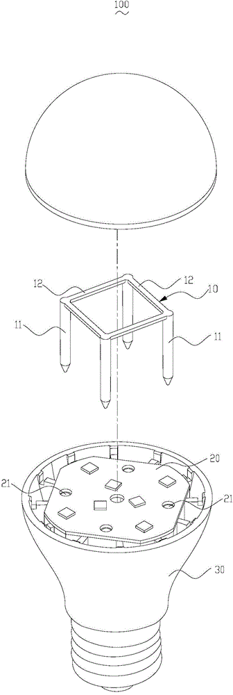
[0015] figure 1 It is an exploded view of the heat transfer rack LED lamp 100 of the present invention. The heat transfer rack LED lamp 100 includes a heat transfer rack 10 , an LED light source board 20 and a heat sink 30 . The LED light source board 20 is disposed on the top of the heat sink 30 . The heat transfer frame passes through the LED light source board 20 and is inserted into the heat sink 30 .

[0016] The heat transfer frame 10 includes at least two pins 11 and a connecting rod 12 connecting these pins. preferred, please refer to figure 1 , the heat transfer frame 10 includes four pins 11, and these connecting rods 12 are connected to each other to form a closed loop. The heat transfer frame 10 is made of metal heat conducting material.

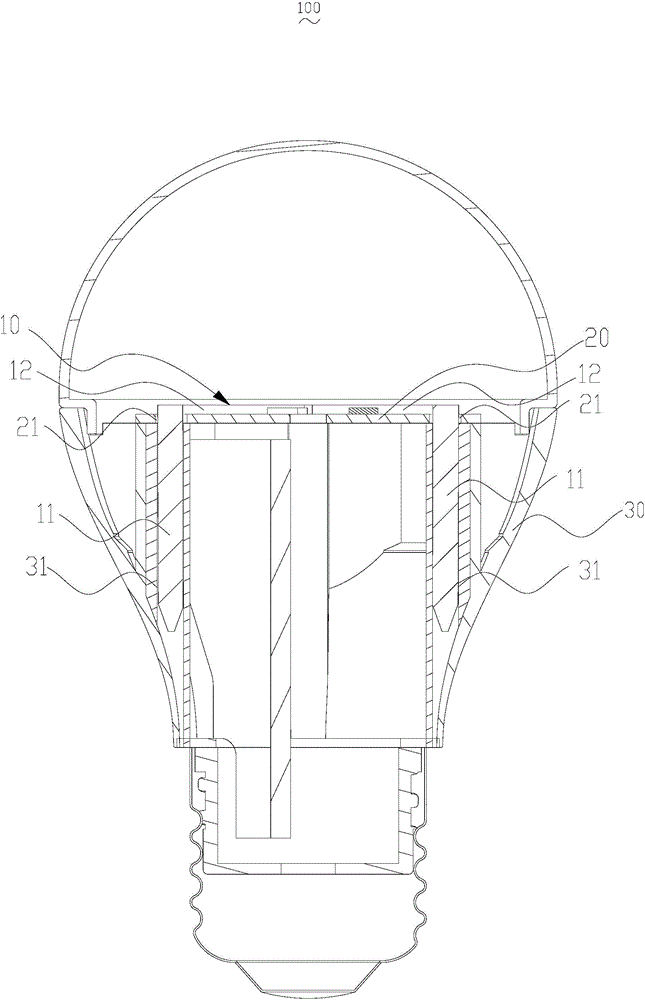
[0017] Please refer to figure 2 , the LED light source board 20 is a thin boa...


PUM


Abstract

The invention discloses a heat transfer frame type LED light which comprises a heat sink and an LED light source plate, the LED light source plate is arranged on the top of the heat sink, the LED light further comprises a heat transfer frame which comprises two or more pins and connecting rods used for connecting the pins, when assembly is conducted, the pins penetrate through the LED light source plate to be inserted into the heat sink, and the connecting rods are connected with the LED light source plate. Due to the fact that the connecting rods increase the contact areas with the LED light source plate, the heat transfer area is increased, and the heat produced by the LED light source plate can be transferred in time, so that the heat transfer frame type LED light has the advantage of being good in heat dissipation effect.

Description

technical field [0001] The invention relates to an LED lighting device, in particular to a heat transfer rack type LED lamp. Background technique [0002] Due to the advantages of energy saving and environmental protection, LED lights are becoming more and more popular, and have the advantages of high luminous efficiency, power saving and long life. When the LED light source emits light, its own temperature will gradually rise. During continuous operation, if the heat generated by the LED light source cannot be dissipated in time, the light source component will be damaged and the service life of the lighting device will be affected. [0003] The current technology is to connect and fix the LED light source board and the heat sink with screws or pins without heat conduction, and there is no device for guiding the heat generated by the LED light source board to the heat sink. For example, a Chinese patent with a publication date of June 20, 2012 and a patent application numb...

Claims


Application Information

Patent Timeline
Patent Type & Authority Applications(China)
IPC IPC(8): F21V29/50F21V17/14F21Y101/02F21Y115/10
CPCF21V17/14
Inventor 曹亮亮李永川
Owner LEEDARSON IOT TECH INC
Why Eureka
Try Eureka