
LED lighting lamp

A technology of LED lighting and LED chips, which is applied in the direction of lighting devices, lighting and heating equipment, lighting device components, etc., can solve the problems of shortening the service life of LED lighting lamps, high heat generation of LED chips, and high requirements for drivers. Solve the problem of glare, soft light, light work effect

Inactive Publication Date: 2015-07-22
上海君能能源科技有限公司
View PDF14 Cites 5 Cited by
  • Summary
  • Abstract
  • Description
  • Claims
  • Application Information

AI Technical Summary

Problems solved by technology

[0004] 1. Since a single LED chip is a point light source, after hundreds of LED chips gather, the light emitted by it has a glare phenomenon, causing discomfort in the lighting environment;
[0005] 2. A large number of LED chips are gathered, which requires a very high-power driver to drive, and the requirements for the driver are relatively high;
[0006] 3. In order to improve the brightness, make the LED chip work at full power, which will lead to the light decay of the LED chip in advance, and the heat generation of the LED chip will be relatively large, which will greatly shorten the service life of the LED lighting lamp

Method used


Image

  • LED lighting lamp

Examples


Embodiment 1

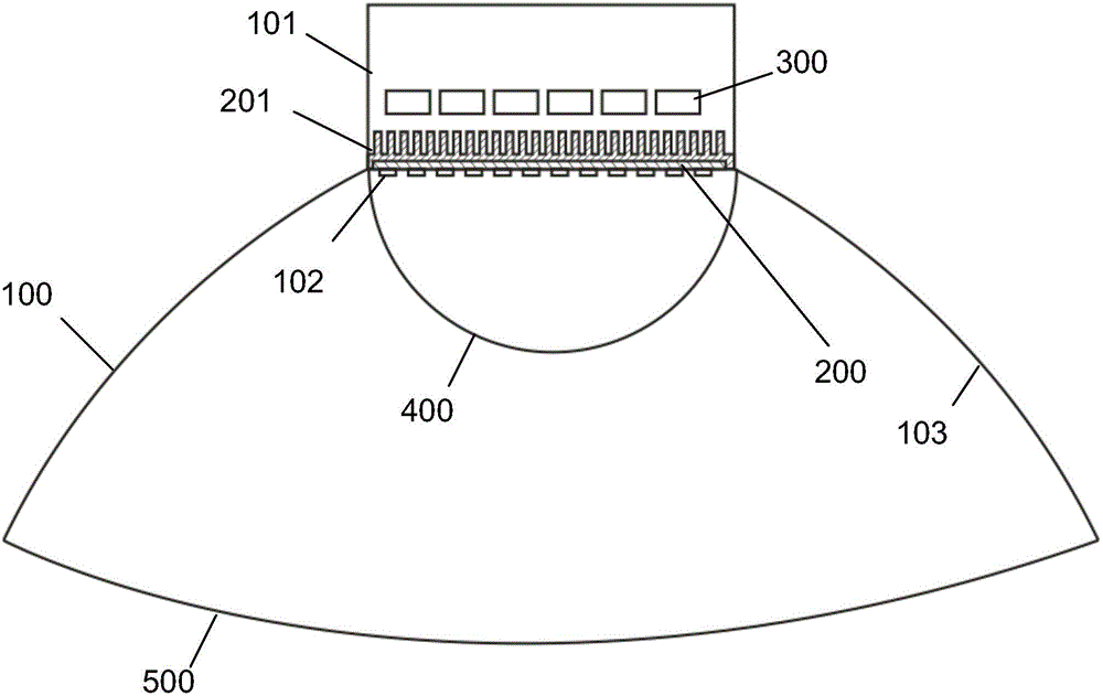
[0020] Such as figure 1 As shown, the LED lighting lamp of the present invention includes a lampshade 100 , a substrate 200 , a power driver 300 , a first light-transmitting cover 400 , and a second light-transmitting cover 500 . The top of the lampshade 100 has a lamp holder 101 , and the substrate 200 is fixed on the mouth of the lamp holder 101 on the top of the lampshade 100 . An aluminum alloy radiator 201 and a power driver 300 are also provided in the space of the lamp holder 101 . The substrate 200 is a disc fixed on the aluminum alloy radiator 201 , and its back is close to the aluminum alloy radiator 201 . LED chips 102 are distributed on the front surface of the substrate 200 .

[0021] In this embodiment, there are 150 LED chips 102 in total, which are divided into 15 groups of 10. Each LED chip 102 is a low-power LED chip with a rated power of only 0.3W, and the total rated power is 45W.

[0022] The lampshade 100 also has a power driver 300 corresponding to th...

Embodiment 2

[0028] In this embodiment, there are 150 LED chips 102 in total, which are divided into 15 groups of 10. Each LED chip 102 is a low-power LED chip with a rated power of only 0.4W, and the total rated power is 60W. Other structures are the same as in Example 1.

[0029] When working, the input power of each LED chip is also controlled to be 80% of the rated power, that is, the input power of each LED chip is controlled at 0.32W, so that all LED chips work under power.

[0030] The actual power of the LED lighting lamp with the above measures is 48W when it is illuminated.

[0031] After comparative experiments, the LED lighting with the above measures, after being turned on for half an hour, the temperature of the radiator is only 41°C; when it is placed at a height of 6.5 meters, the illuminance measured on the ground reaches 52Lux; while the LED lighting that does not adopt the above measures LED lighting (LEDs are not grouped, use high-power LED chips, total power 50W, full...


PUM


Abstract

The invention discloses an LED lighting lamp. The LED lighting lamp comprises a lampshade, power drivers, a substrate fixedly arranged in the lampshade and a plurality of LED chips distributed on the front face of the substrate. A first light-pervious cover which covers the substrate and the LED chips and protrudes outwards in a circular-arc manner is arranged in the lampshade, and a second light-pervious cover is arranged on an opening portion of the lampshade; a reflecting mirror surface is arranged on the inner surface of the lampshade; the LED chips are small-power LED chips with the rated power ranging from 0.3w to 0.4w, and a divided into multiple groups in a manner of the total rated power of 3W to 4W in each group; and the multiple power drivers are arranged, and the number of the power drivers corresponds to the group number of the LED chips. Each power driver drives a group of LED chips, and in the working process, the power drivers control the input power of each LED chip to be 70 percent to 80 percent of the rated power. The LED lighting lamp has the advantages of being high in brightness, small in heating amount and low in requirement of the power drivers, and the service life of the LED lighting lamp is prolonged.

Description

technical field [0001] The invention belongs to the technical field of LED lighting lamps, in particular to an LED lighting lamp. Background technique [0002] LED (Light-Emitting-Diode, which means light-emitting diode in Chinese) is a semiconductor that can convert electrical energy into visible light. LED lighting is an emerging industry that has developed in recent years. It can be called another lighting revolution since the advent of incandescent lamps in the 19th century. The third generation of lighting source after sodium lamp, etc.). It changes the principle of traditional incandescent lamp tungsten light emission and energy-saving lamp three-color fluorescent light emission, and uses electric field to emit light at room temperature and low voltage. Compared with traditional lighting sources, LED lighting has a series of advantages such as higher education, energy saving, environmental protection, and long life, especially in terms of energy saving and environmen...

Claims


Application Information

Patent Timeline
Patent Type & Authority Applications(China)
IPC IPC(8): F21S2/00F21V3/04F21V29/503F21V29/89F21Y101/02F21K9/20F21Y115/10
CPCF21S2/00F21V3/02F21V23/003
Inventor 徐君龙
Owner 上海君能能源科技有限公司
Learn More