Eureka AIR delivers breakthrough ideas for toughest innovation challenges, trusted by R&D personnel around the world.

Shaft seal auxiliary flushing system for centrifugal pump and axial flow pump

A technology for flushing systems and axial flow pumps, applied to parts, pumps, pump elements, etc. of pumping devices for elastic fluids, which can solve problems such as burnout, failure to provide a backup pump 2 seal flushing scheme, and increased friction

Active Publication Date: 2017-06-16
邢宇
View PDF6 Cites 0 Cited by
  • Summary
  • Abstract
  • Description
  • Claims
  • Application Information

AI Technical Summary

Problems solved by technology

In mild cases, the mechanical seal will be burned immediately, causing the pump to leak quickly, and the pump must be stopped for processing, thus affecting production
Seriously, it will lead to fire and cause hidden dangers to safety production.
[0013] (5) Due to the deposition of the material in the pump casing and the sealing chamber of the spare pump that has been stopped for a long time on the surface of the part and the contact material, especially the auxiliary seal ring on the mechanical seal elastic compensation component and the parts that are in contact with it Some solidified or even carbonized materials are deposited on the corresponding position of the shaft to form a flange between the shaft and the sealing ring, which hinders the normal operation of the compensation components and reduces the following ability. Every time the sealing ring moves slightly on the shaft Both have to jump over this flange, so the friction between them increases sharply, quickly damaging the sealing ring and causing leakage
And there is no seal flushing scheme to protect the standby pump 2 that is out of operation

Method used


Image

  • Shaft seal auxiliary flushing system for centrifugal pump and axial flow pump
  • Shaft seal auxiliary flushing system for centrifugal pump and axial flow pump
  • Shaft seal auxiliary flushing system for centrifugal pump and axial flow pump

Examples


Embodiment Construction

[0052] A centrifugal pump and an axial-flow pump auxiliary flushing system for shaft seals of the present invention will be described in detail below with reference to the embodiments and the accompanying drawings.

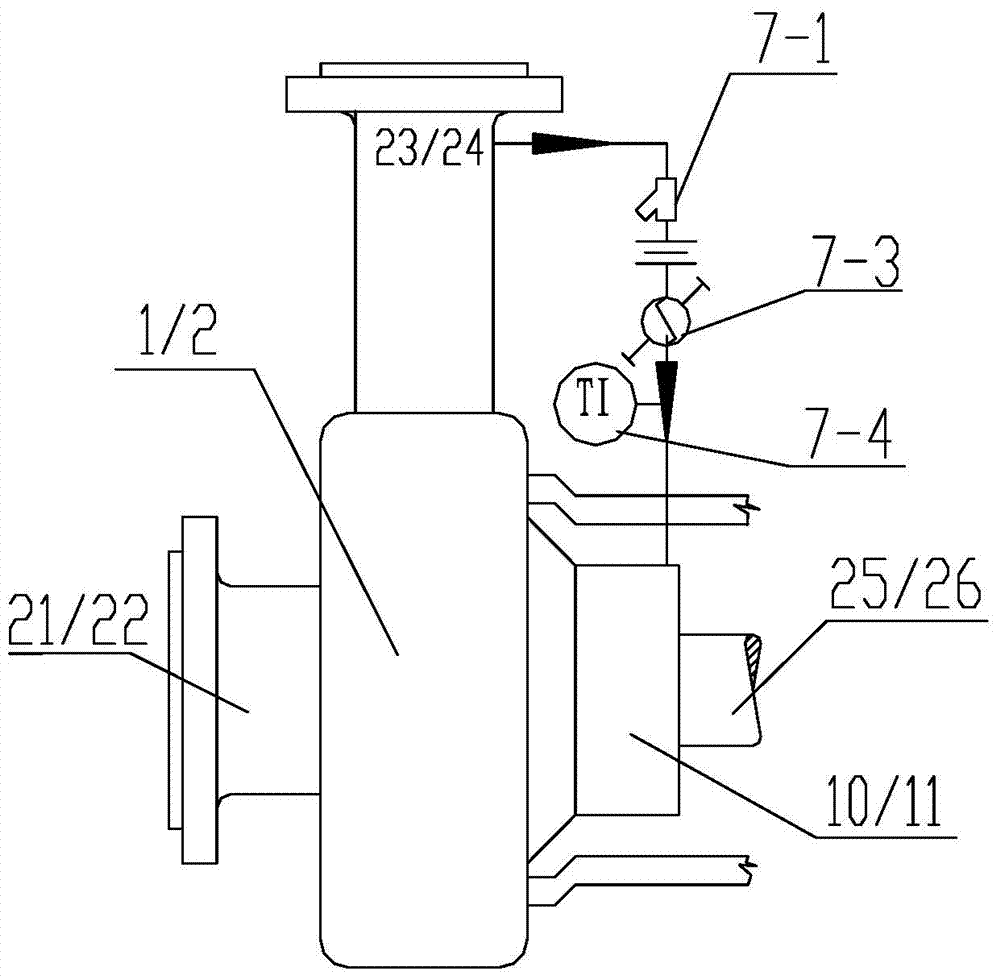
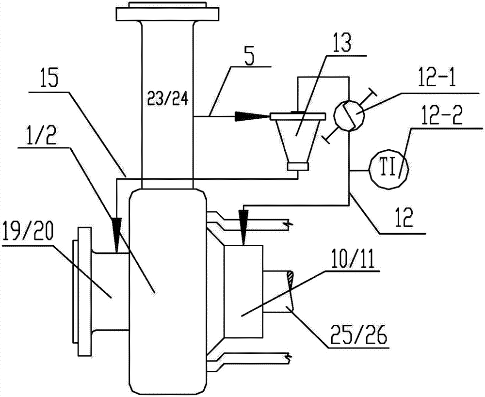
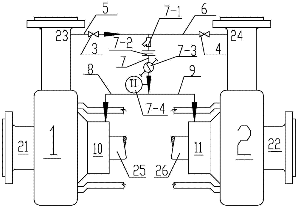
[0053] A shaft seal auxiliary flushing system of a centrifugal pump and an axial flow pump of the present invention is in such as figure 1 , figure 2 What is realized on the basis of the prior art shown is that the washing systems of the main operating pump and the standby pump of the prior art are connected in parallel to realize. A shaft seal auxiliary flushing system of a centrifugal pump and an axial flow pump of the present invention, specifically as image 3 , Figure 4 As shown, it includes: the main operating pump 1 and the backup pump 2 respectively provided with the same shaft seal flushing system, the shaft seal flushing system of the main operating pump 1 and the shaft seal flushing system of the backup pump 2 are connected in parallel to form a mut...


PUM


Abstract

A shaft seal auxiliary flushing system for a centrifugal pump and for an axial-flow pump, provided with a main operating pump (1) and a standby pump (2) respectively provided with identical shaft seal flushing systems. The shaft seal flushing system of the main operating pump (1) and the shaft seal flushing system of the standby pump (2) are connected in parallel with each other to constitute common shaft seal flushing systems that are in communication with each other. The common shaft seal flushing systems are such that: a first water outlet pipe (5) connected onto a water outlet (23) of the main operating pump (1) and a first opening / closing valve (3) provided on the first water outlet pipe (5) and used for controlling outflow of flushing water, a second water outlet pipe (6) connected onto a water outlet (24) of the standby pump (2) and a second opening / closing valve (4) provided on the second water outlet pipe (6) and used for controlling outflow of flushing water, and a first fluid guide pipe (7) connected onto a water outlet of the first water outlet pipe (5) and that of the second water outlet pipe (6), where a water outlet of the first fluid guide pipe (7) is respectively connected to a flushing water inlet on a sealing gland (10) of the main operating pump (1) via a third water outlet pipe (8) and to a flushing water inlet on a sealing gland (11) of the standby pump (2) via a fourth water outlet pipe (9). Fluid material parameters in sealed cavities of the main and standby pumps can be kept identical at all times by means of the flushing system.

Description

technical field [0001] The invention relates to a pump shaft seal flushing system. In particular, it relates to a shaft seal auxiliary flushing system of a centrifugal pump and an axial flow pump. Background technique [0002] Centrifugal pumps in chemical processes play an extremely important role in the field of oil refining and chemical equipment. How to prolong the service life of mechanical seals is an important topic for our current research. According to API682 Appendix D (standard appendix) standard flushing scheme and auxiliary metal components In 1.3 Sealing performance requirements, the seals that meet this standard should meet the following performances: [0003] (1) The continuous operating life of all seals is not less than 25,000 hours; [0004] (2) Under the condition that the pressure of the suppression seal chamber is not higher than the leakage pressure value set by the pressure switch [gauge pressure ≤ 0.7bar (10psi)], the continuous operation life is n...

Claims


Application Information

Patent Timeline
IPC IPC(8): F04D29/70
CPCF04D29/70
Inventor 邢宇邢天宜
Owner 邢宇
Why Eureka
Eureka Blog
Learn More