
Delayed ignition control device

A delayed ignition and control device technology, applied in the direction of electric spark ignition controller, engine ignition, ignition generator rotor, etc., can solve the problems of speeding phenomenon, power reduction, increased energy consumption, etc., to achieve easy delay time, reliable operation, The effect of simple structure

Inactive Publication Date: 2015-07-22
YUYAO AOXIN ELECTRICAL APPLIANCE
View PDF7 Cites 1 Cited by
  • Summary
  • Abstract
  • Description
  • Claims
  • Application Information

AI Technical Summary

Problems solved by technology

[0003] When the speed of a general-purpose small gasoline engine exceeds the maximum power point of the engine, the power will decrease and increase energy consumption. Excessively high speed will reduce the mechanical life of the engine. The speed of a general-purpose small gasoline engine will often increase suddenly when it is idling, causing speeding phenomenon and critical operation personal safety

Method used


Image

  • Delayed ignition control device
  • Delayed ignition control device
  • Delayed ignition control device

Examples


Embodiment Construction

[0019] The present invention is described below with reference to the accompanying drawings. Similar parts are denoted by the same reference numerals.

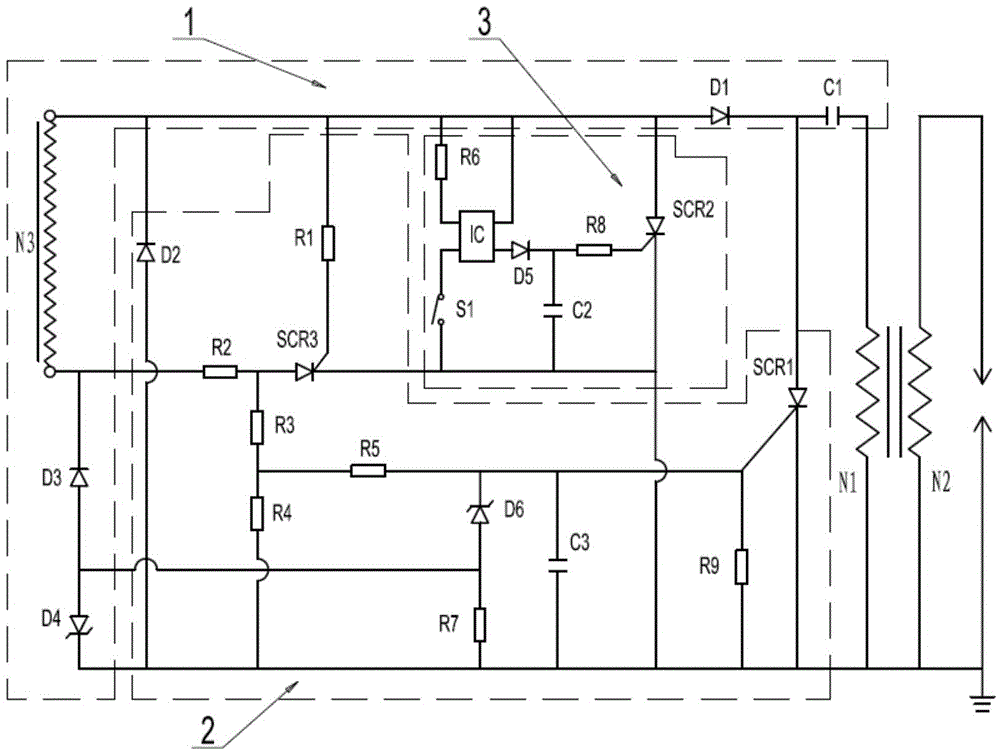
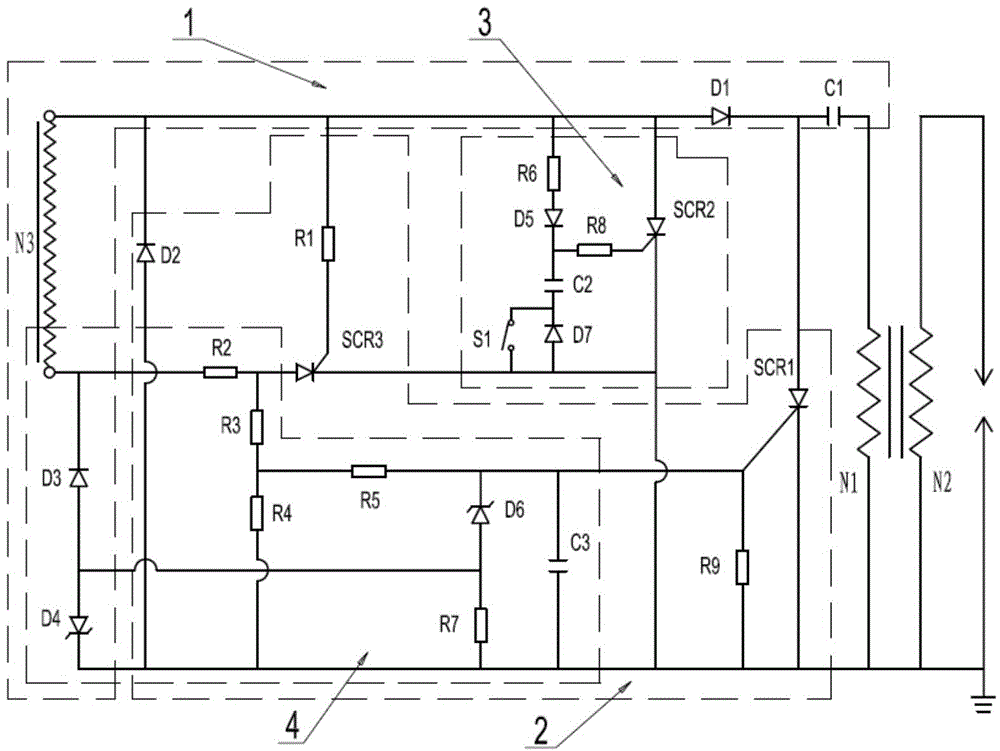
[0020] figure 1 It shows the schematic circuit diagram of the first embodiment of the present invention. The delayed ignition control device of the present invention includes: a charging circuit 1 , an ignition timing control circuit 2 and a delayed ignition control circuit 3 .

[0021] The charging circuit 1 includes a power supply coil N3, an energy storage capacitor C1, a diode D1, a diode D3 and a regulator tube D4. The power coil N3 is connected to an external power supply, the anode of the diode D1 is connected to the beginning of the power coil N3, and the cathode is connected to the energy storage capacitor C1. The other end of the energy storage capacitor C1 is connected to one end of the ignition coil N1, and the end of the power supply coil N3 is connected to the other end of the ignition coil N1 and grounded. Th...


PUM


Abstract

A delayed ignition control device comprises a charging circuit (1) and a delayed ignition control circuit (3). The charging circuit (1) comprises a power supply circuit N3, an energy storage capacitor C1 and a diode D1, wherein the positive electrode of the diode D1 is connected with the start end of the power supply coil N3, the negative electrode of the diode D1 is connected with the energy storage capacitor C1, and the other end of the energy storage capacitor C1 is connected with an ignition coil. The delayed ignition control circuit (3) comprises a silicon controlled rectifier SCR2, an optical coupler IC, a diode D5, a voltage keeping capacitor C2, a flameout switch S1, a resistor R6 and a resistor R8, wherein the resistor R6 is connected between the positive electrode of the input end of the optical coupler IC and the start end of the power supply coil N3, the flameout switch S1 is connected between the negative electrode of the input end of the optical coupler IC and the ground, the collector of the optical coupler IC is connected with the start end of the power supply coil N3, the output end of the optical coupler IC is connected with the positive electrode of the diode D5, the voltage keeping capacitor C2 is connected between the negative electrode of the diode D5 and the ground, and the resistor R8 is connected between the negative electrode of the diode D5 and the control electrode of the silicon controlled rectifier SCR2. The delayed ignition control device has the advantages of being simple in structure, capable of easily adjusting the delayed time and reliable in operation.

Description

technical field [0001] The invention relates to an ignition device, in particular to an ignition control device with a delayed ignition function. Background technique [0002] Existing forestry machinery chain saw etc. basically all use general-purpose small gasoline engine as power, when needing to stop, basically all are to cut off the electric current in the power supply coil of magneto ignition control device with the flameout switch of button device, be exactly directly The power coil is short-circuited, causing the power coil to stop working. But as soon as the button is released, the ignition returns to normal and the engine continues to spin. Since the chain saw basically works manually, if the operator presses the flameout switch button and then releases the flameout switch during the logging process, the engine will start running again immediately after a temporary stop, and the sudden impact The power will damage the chain saw and endanger the personal safety of...

Claims


Application Information

Patent Timeline
Patent Type & Authority Applications(China)
IPC IPC(8): F02P5/00
CPCF02P5/00F02P1/005F02P1/02F02P1/086F02P3/06
Inventor 倪蛟虹倪剑鸣陈晓明
Owner YUYAO AOXIN ELECTRICAL APPLIANCE
Learn More