
A tamper-resistant lock based on a screw-type back-clutch module and a dual-motor module

A screw-type, dual-motor technology, applied in the field of tamper-proof locks, can solve the problems of motor stuck and burnt, easy to open door lock, large contact area of ​​spring wire, etc., so as to reduce the risk of stopping work and increase safety and security. high sex effect

Active Publication Date: 2017-03-01
718TH RES INST OF CHINA SHIPBUILDING INDAL CORP
View PDF5 Cites 0 Cited by
  • Summary
  • Abstract
  • Description
  • Claims
  • Application Information

AI Technical Summary

Problems solved by technology

The structure of the door lock with the clutch on the front panel is simple, but the front panel is damaged, and it is easy to open the door lock when the front panel is removed; the lock body of the door lock with the clutch inside the lock body is an electric lock body, and there is a signal on the lock body Cables, power supply lines, the installation of the lock body is more troublesome, and due to the addition of electrical components, the reliability of the lock body is reduced
In the prior art, the inner part of the lock is a force-bearing part that receives the action of opening and closing the door. It is provided with a square force-bearing hole that is completely matched with the square steel. When the front panel is destroyed, the lock body is exposed, and the lock can be driven by turning the square steel. The parts in the body rotate to realize unlocking, so the lock body can be opened easily, and the security of the door lock is not high
Moreover, during the movement of the motor pushing plate in the prior art, since the top of the horizontal axis is a plane and has a large contact area with the spring wire, the cross bar may block the torsion spring spring wire, causing the motor to be unable to rotate, and the motor is stuck. burn out problem

Method used


Image

  • A tamper-resistant lock based on a screw-type back-clutch module and a dual-motor module
  • A tamper-resistant lock based on a screw-type back-clutch module and a dual-motor module
  • A tamper-resistant lock based on a screw-type back-clutch module and a dual-motor module

Examples


Embodiment Construction

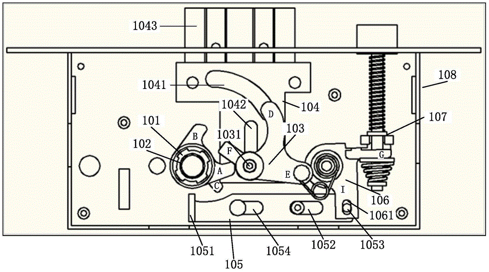
[0032] The tamper-resistant lock based on the screw-type back-clutch module and the double-motor module of the present invention includes: a lock body module, a screw-type back-clutch module and a double-motor module; wherein,

[0033] Such as figure 1As shown, the lock body module of the present invention includes: a main bolt shifting block 101, an anti-pry sleeve 102, a main bolt shifting rod 103, a main dead bolt assembly 104, an oblique bolt connecting rod assembly 105, and an oblique bolt shifting rod 106 , oblique bolt assembly 107, lock body box 108, cylindrical shaft and torsion spring. Such as figure 2 As shown, the main bolt shifting block 101 is provided with a first extension arm A, a second extension arm B, and a third extension arm C; and the axial center position of the main bolt shifting block 101 is provided with a sleeve through hole , and the inner peripheral surface is provided with an axial slot matching with the transmission assembly; one end of the t...


PUM


Abstract

The invention provides a burglary-resistant lock based on a spiral type reverse clutch module and a double-motor module. The burglary-resistant lock is characterized by comprising a lock body module, the spiral type reverse clutch module and the double-motor module. The spiral type reverse clutch module comprises a lifting pin (207), a lifting pin spring (208), a lifting pin baffle ring (206), an inner handle rotating part (205), a square steel sleeve (204) and a transmission assembly. The double-motor module comprises a covering plate (301), two pinions (302), a gear shaft (303), a motor shell (304), two identical motors (305), a torsion spring (306), an arc push plate (307), a front push plate (308), a rear push plate (309) and a transverse rod (3010). The burglary-resistant lock is unlocked in a single direction, the lock body still can not be unlocked under the condition that a front panel is detached and the lock body is exposed, so that the safety of the lock is improved.

Description

technical field [0001] The invention belongs to the technical field of products, and in particular relates to a tamper-resistant lock based on a spiral back clutch module and a double motor module. Background technique [0002] At present, most of the clutch mechanisms of electronic door locks on the market are located on the front panel of the door lock or inside the lock body. The structure of the door lock with the clutch on the front panel is simple, but the front panel is damaged, and it is easy to open the door lock when the front panel is removed; the lock body of the door lock with the clutch inside the lock body is an electric lock body, and there is a signal on the lock body Wires, power supply lines, and the installation of the lock body are cumbersome, and due to the addition of electrical components, the reliability of the lock body decreases. In the prior art, the inner part of the lock is a force-bearing part that receives the action of opening and closing th...

Claims


Application Information

Patent Timeline
Patent Type & Authority Patents(China)
IPC IPC(8): E05B47/00E05B63/14E05B17/20E05B15/00E05B15/10
Inventor 陈正华吴勇张重阳孟涛卢荣
Owner 718TH RES INST OF CHINA SHIPBUILDING INDAL CORP
Learn More