
Front and back vehicle prompting rear-end collision prevention system based on visible light communication technology

A technology for visible light communication and rear-end collision prevention, applied in vehicle components, optical signals, closed-circuit television systems, etc., can solve problems such as system electromagnetic interference, complicated wiring, and excessive wiring harnesses in the car, and achieve the effect of improving comfort and safety.

Active Publication Date: 2015-07-22
ROPEOK TECHNOLOGY GROUP CO LTD
View PDF5 Cites 6 Cited by
  • Summary
  • Abstract
  • Description
  • Claims
  • Application Information

AI Technical Summary

Problems solved by technology

However, the lights are only controlled by independent switches, and the amount of information is single, so they cannot synthesize the basic driving state of the car and provide more comprehensive information for the driver behind.
At the same time, the light has only two states of on and off, the warning effect provided is not good enough, and the occurrence of traffic accidents cannot be effectively avoided
Finally, the traditional lighting control system mostly adopts relay or independent switch mode control, which makes the wiring harness in the car too much and the wiring is complicated, which will cause serious electromagnetic interference to the system and reduce the reliability of the system
[0004] At the same time, if there are many vehicles in front, or there are large vehicles in front, it will lead to the situation that traffic lights cannot be seen

Method used


Image

  • Front and back vehicle prompting rear-end collision prevention system based on visible light communication technology

Examples


Embodiment Construction

[0024] In order to make the objects and advantages of the present invention clearer, the present invention will be further described in detail below in conjunction with the examples. It should be understood that the specific embodiments described here are only used to explain the present invention, not to limit the present invention.

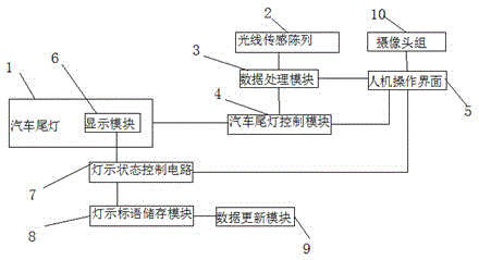
[0025] Such as figure 1 As shown, the embodiment of the present invention provides a rear-end collision prevention system based on visible light communication technology, which is characterized in that it includes

[0026] A light sensing array 2, installed on the front of the vehicle, including 1-10 color sensors, used to detect the distance between target vehicles and the color of road traffic lights, and send detection information;

[0027] The camera group 10 is used to collect the picture information of the light sign slogan of the front taillight 1, and send the picture information;

[0028] The automobile taillight control module 4 is u...


PUM


Abstract

The invention discloses a front and back vehicle prompting rear-end collision prevention system based on the visible light communication technology. The front and back vehicle prompting rear-end collision prevention system comprises a light ray sensing array used for detecting vehicle distance of target vehicles and the color of a traffic light and sending detection information, a camera set used for collecting image information of a lamp indication slogan of tail lights of the front vehicle and sending the image information, an automobile tail light control module, a data processing module used for processing the information, detected through the light ray sending array, of the traffic light and the vehicle distance detected through the light ray sending array, transmitting the information and the vehicle distance to an automobile tail light control module, processing the flicker frequency of the tail lights of the front vehicle and the image information collected and sent by the camera set and conducting displaying on a man-machine operation interface, and a light indication state control circuit. The vehicle distance of the target vehicles and the color of the traffic light are detected through visible light, and by setting the slogan indicated by the tail lights of the front vehicles and recognizing the lamp indication slogan of the tail lights of the front vehicle through the camera set, driving comfort and safety are greatly improved.

Description

technical field [0001] The invention relates to the field of automobile rear-end collision prevention, in particular to an anti-rear-end collision system for prompting front and rear vehicles based on visible light communication technology. Background technique [0002] In the existing automotive lighting and signal control system, when the driver depresses the brake pedal, the brake light switch is closed, and the brake tail light and high-position brake light of the car are turned on; when the driver toggles the turn signal switch, the The turn signals light up accordingly; when the driver puts the reverse gear, that is, the reverse light switch is closed, the reverse lights light up. Different car lights represent different light language. [0003] In the normal driving of the front and rear cars, the tail light group of the front car will display different signal lights according to the different operations of the driver on the car signal light switch. However, the lam...

Claims


Application Information

Patent Timeline
IPC IPC(8): B60Q1/30B60Q1/50
CPCH04N7/18B60Q1/30B60R1/00B60R16/0231B60R2300/80Y02B20/40
Inventor 周午贤
Owner ROPEOK TECHNOLOGY GROUP CO LTD
Learn More