
Catenary suspension linear ultrasound longitudinal vibration amplitude-change bar with hole formed in axial direction of output end

A horn and output technology, applied in the field of mechanical vibration, can solve the problems of shortening the service life of the transducer, increasing the input electric power of the transducer, limited amplitude amplification factor, etc., to achieve the effect of improving work efficiency

Inactive Publication Date: 2015-07-22
SHAANXI NORMAL UNIV
View PDF6 Cites 6 Cited by
  • Summary
  • Abstract
  • Description
  • Claims
  • Application Information

AI Technical Summary

Problems solved by technology

The amplitude amplification factor of the traditional solid horn with variable cross-section is limited, and it often cannot meet the requirements for large-amplitude power ultrasonic applications.
The first solution is to cascade multi-stage horns together, the second is to increase the input power of the transducer, the first method will increase the cost, and the second method will shorten the transducer service life

Method used


Image

  • Catenary suspension linear ultrasound longitudinal vibration amplitude-change bar with hole formed in axial direction of output end
  • Catenary suspension linear ultrasound longitudinal vibration amplitude-change bar with hole formed in axial direction of output end
  • Catenary suspension linear ultrasound longitudinal vibration amplitude-change bar with hole formed in axial direction of output end

Examples


Embodiment 1

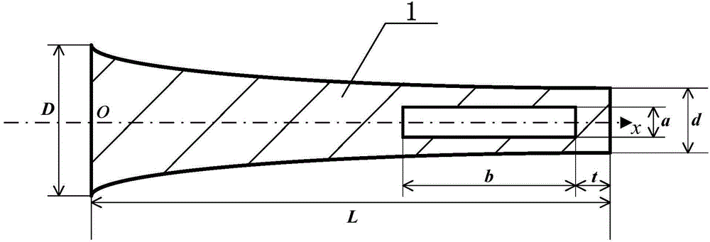
[0017] exist figure 1 Among them, the catenary-shaped ultrasonic longitudinal vibration horn with an axial opening at the output end of the present invention is composed of the horn 1 . In this example, the two ends of the horn 1 are parallel planes perpendicular to the center line, and the side is a rod-shaped body with a hyperbolic cosine rotation surface. The geometric shape of the side is a curve in the rectangular coordinate system

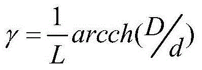
[0018] y=(d / 2)chγ(L-x), where γ = 1 L arcch ( D / d )

[0019] is the rotating surface formed by the generatrix and the x-axis is the rotation axis, 0≤x≤length L of the horn, where y is the radius of the cross-section at the coordinate x, and D is the diameter of the large end of the horn 1. When in use, change The large end of the horn 1 is connected to the ultrasonic transducer, d is the diame...

Embodiment 2

[0022] In this example, the two ends of the horn 1 are parallel planes perpendicular to the center line, and the side is a rod-shaped body with a hyperbolic cosine rotation surface. The geometric shape of the side is a curve in the rectangular coordinate system

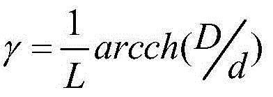
[0023] y=(d / 2)chγ(L-x), where γ = 1 L arcch ( D / d )

[0024] is the rotating surface formed by the generatrix and the x-axis is the rotation axis, 0≤x≤length L of the horn, where y is the radius of the section at the coordinate x, D is the diameter of the large end of the horn 1, and the length of the horn 1 The big end is the input and the little end is the output. The horn length L, the diameter D of the large end of the horn 1, the geometrical dimensions of the diameter d of the small end of the horn 1, and the materials used in this embodiment are the same as in Exa...

Embodiment 3

[0026] In this example, the two ends of the horn 1 are parallel planes perpendicular to the center line, and the side is a rod-shaped body with a hyperbolic cosine rotation surface. The geometric shape of the side is a curve in the rectangular coordinate system

[0027] y=(d / 2)chγ(L-x), where γ = 1 L arcch ( D / d )

[0028] is the rotating surface formed by the generatrix and the x-axis is the rotation axis, 0≤x≤length L of the horn, where y is the radius of the section at the coordinate x, D is the diameter of the large end of the horn 1, and the length of the horn 1 The big end is the input and the little end is the output. The horn length L, the diameter D of the large end of the horn 1, the geometrical dimensions of the diameter d of the small end of the horn 1, and the materials used in this embodiment are the same as in Exa...


PUM


Abstract

Provided is a catenary suspension linear ultrasound longitudinal vibration amplitude-change bar with a hole formed in the axial direction of the output end. The rectangular through hole is machined in the inner side of the small end in the axial direction of the center line of the amplitude-change bar, the distance t between the outer wall of the rectangular through hole and the small end is 2 mm-0.18 mm, the length of the amplitude-change bar is L, and according to the geometric shape, the amplitude-change bar is a rod-like body with the two end faces being parallel planes perpendicular to the center line and the side face being a hyperbolic cosine revolution surface. Because the rectangular through hole is formed in the position, away from the output end by a certain distance, in the axial direction of the center line of the catenary suspension linear amplitude-change bar, when the amplitude-change bar works at a longitudinal vibration resonant frequency position, the output end further has excited bending vibration components besides longitudinal vibration components of the amplitude-change bar; due to the superposition of the longitudinal vibration components and the bending vibration components, the amplitude amplification coefficient of the holed conical amplitude-change bar is increased by 1.68-3.3 times compared with that of a solid conical amplitude-change bar, and working efficiency is greatly improved.

Description

technical field [0001] The invention belongs to the technical field of mechanical vibration, and in particular relates to an ultrasonic horn of an ultrasonic transducer. Background technique [0002] Ultrasonic horn can be widely used in chemical industry, petroleum, cleaning, mechanical processing, food, medicine, automobile, instrumentation, textile, mechanical processing (such as turning, drilling, grinding, plastic welding, metal welding) and other fields. It is an important component in the ultrasonic vibration system. It is connected with the ultrasonic transducer. Its main function is to amplify the particle displacement or velocity of the mechanical vibration output by the ultrasonic transducer, and to concentrate the ultrasonic energy on the area of ​​the output end of the horn. It plays the role of energy gathering, also known as gear lever or energy concentrator. Usually the amplitude of the output end of the ultrasonic transducer is small, only a few microns, an...

Claims


Application Information

Patent Timeline
Patent Type & Authority Applications(China)
IPC IPC(8): B06B3/02
Inventor 贺西平
Owner SHAANXI NORMAL UNIV
Learn More