
Two-chamber type regenerative catalytic organic waste gas purification device having back blowing function

A technology for organic waste gas and catalytic purification, applied in the field of air pollution control, can solve the problems of increased quantity, complex control, increased investment, etc., and achieve the effects of low cost, improved purification efficiency and simple structure

Inactive Publication Date: 2015-07-08
SOUTH CHINA UNIV OF TECH
View PDF4 Cites 12 Cited by
  • Summary
  • Abstract
  • Description
  • Claims
  • Application Information

AI Technical Summary

Problems solved by technology

However, due to the addition of a reaction chamber, the number of catalysts, heat storage bodies, valves, and pipelines increases, the control is more complicated, and the investment increases a lot.

Method used


Image

  • Two-chamber type regenerative catalytic organic waste gas purification device having back blowing function
  • Two-chamber type regenerative catalytic organic waste gas purification device having back blowing function
  • Two-chamber type regenerative catalytic organic waste gas purification device having back blowing function

Examples


Embodiment Construction

[0021] The purpose of the invention will be described in further detail below in conjunction with the drawings and specific embodiments. The embodiments cannot be repeated here, but the implementation of the invention is not limited to the following embodiments.

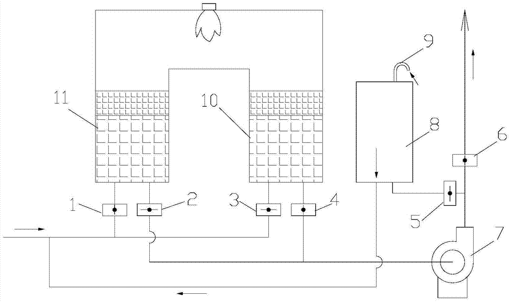
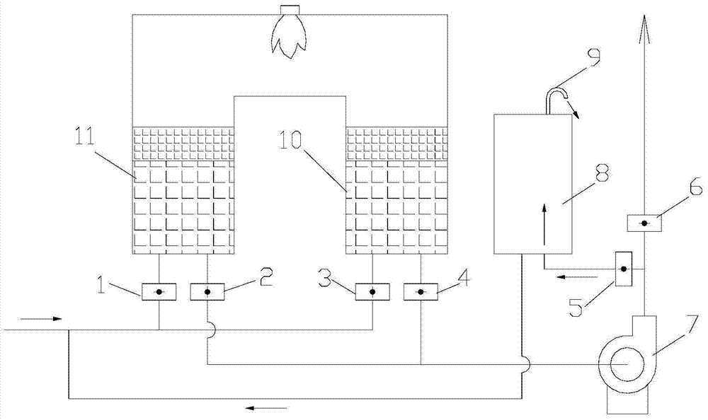
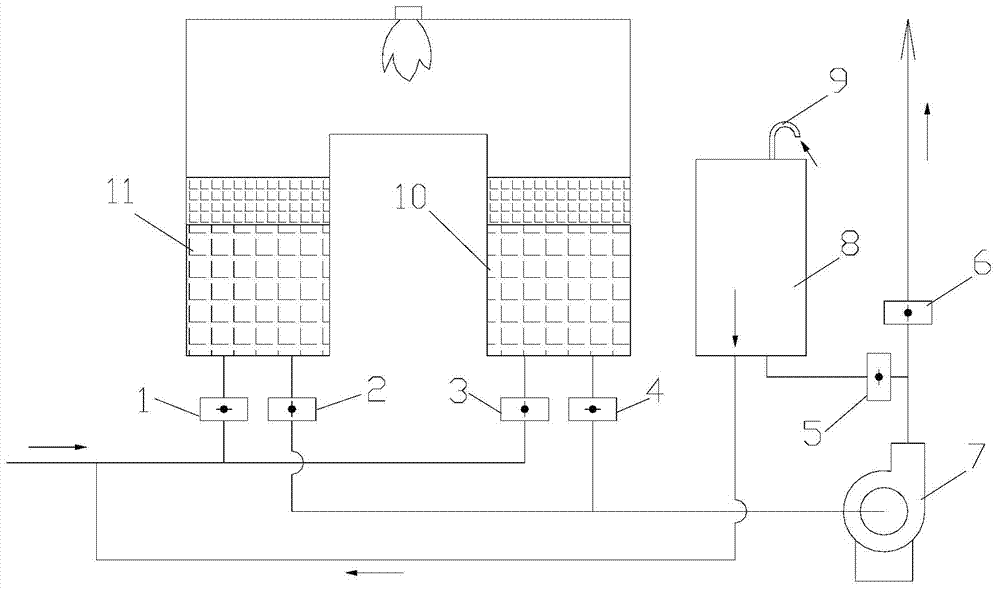
[0022] A two-chamber thermal storage catalytic and purification device with back-blowing function includes a two-chamber thermal storage catalytic combustion device having a first thermal storage catalytic reaction chamber 11 and a second thermal storage catalytic reaction chamber 10. The first heat storage catalytic reaction chamber 11 and the second heat storage catalytic reaction chamber 10 are both filled with a ceramic heat storage body layer and a catalyst layer. The first heat storage catalytic reaction chamber 11 and the second heat storage catalytic reaction chamber The air inlet of 10 is connected to the organic waste gas inlet pipe through the first valve 1 and the third valve 3 respectively, and further inclu...


PUM


Abstract

The invention discloses a two-chamber type regenerative catalytic organic waste gas purification device having a back blowing function. The two-chamber type regenerative catalytic organic waste gas purification device comprises a two-chamber type regenerative catalytic combustion device provided with a first regenerative catalytic reaction chamber and a second regenerative catalytic reaction chamber, wherein a gas inlet of the first regenerative catalytic reaction chamber and a gas inlet of the second regenerative catalytic reaction chamber are respectively connected with organic waste gas inlet pipes through a first valve and a third valve. The two-chamber type regenerative catalytic organic waste gas purification device further comprises a back blowing chamber and a fan, wherein the back blowing chamber is connected with the organic waste gas inlet pipes of the two-chamber type regenerative catalytic organic waste gas purification device through pipes, an exhaust port of the fan is communicated with the back blowing chamber through a pipe and a fifth valve and meanwhile is communicated with the atmosphere through a sixth valve, an air inlet of the fan is connected with a gas outlet of the first regenerative catalytic reaction chamber through a pipe and a second valve and is connected with a gas outlet of the second regenerative catalytic reaction chamber through a pipe and a fourth valve. The two-chamber type regenerative catalytic organic waste gas purification device is provided with the external back blowing chamber, waste gas 'short circuit' situations are decreased, purification rate is effectively improved, and the two-chamber type regenerative catalytic organic waste gas purification device is simple in structure, low in cost, easy to process and easy to control.

Description

Technical field [0001] The invention belongs to the technical field of air pollution control, and relates to an organic waste gas treatment device, in particular to a two-chamber heat storage catalytic purification device with a back blow function. Background technique [0002] Catalytic combustion is a widely used medium and high concentration organic waste gas purification technology. Its principle is to use a catalyst to oxidize and decompose volatile organic compounds into CO at a lower temperature. 2 And H 2 O, and the heat of reaction is released at the same time. The reaction temperature is usually 250~500℃. [0003] Generally, in the catalytic combustion process, the exhaust gas passes through a heat exchanger to increase the temperature, and then the temperature of the exhaust gas reaches the catalytic reaction temperature through electric heating or fuel combustion. The reacted gas passes through a heat exchanger to transfer heat to the unreacted gas. Due to the low heat...

Claims


Application Information

Patent Timeline
IPC IPC(8): F23G7/07
CPCF23G7/07F23G2209/14
Inventor 吴军良肖海麟孙西勃付名利叶代启
Owner SOUTH CHINA UNIV OF TECH
Learn More