
Vapor deposition method and vapor deposition device

A technology of evaporation and evaporation materials, which is applied in the directions of vacuum evaporation plating, sputtering plating, ion implantation plating, etc., can solve the problems of affecting the accuracy of evaporation, the gravity of the mask plate is large, and the accuracy of evaporation is reduced. Achieve the effect of improving the precision of evaporation

Inactive Publication Date: 2015-07-08
BOE TECH GRP CO LTD
View PDF4 Cites 9 Cited by
  • Summary
  • Abstract
  • Description
  • Claims
  • Application Information

AI Technical Summary

Problems solved by technology

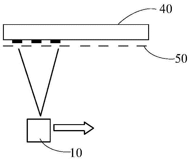
like Figure 1a and Figure 1b It is a schematic diagram of evaporation scanning in the prior art. Usually, the temperature of the evaporation source is higher, so that the evaporation material can be evaporated towards the substrate at a faster speed, but the high temperature will make the mask plate 50 and the target substrate 40 A certain deformation occurs, which leads to a decrease in the deposition accuracy
On the other hand, in order to make the thickness of the target film layer 60 formed on the target substrate more uniform during the line source evaporation scanning, the evaporation source 10 is usually arranged under the target substrate 40 and the mask plate 50, and is aligned from bottom to top. The target substrate is evaporated, but due to the high gravity of the mask plate, a large gap will be generated between the middle position of the target substrate 40 and the mask plate 50, thereby affecting the evaporation accuracy.

Method used


Image

  • Vapor deposition method and vapor deposition device
  • Vapor deposition method and vapor deposition device
  • Vapor deposition method and vapor deposition device

Examples


Embodiment Construction

[0029] Specific embodiments of the present invention will be described in detail below in conjunction with the accompanying drawings. It should be understood that the specific embodiments described here are only used to illustrate and explain the present invention, and are not intended to limit the present invention.

[0030] As an aspect of the present invention, a kind of vapor deposition method is provided, such as figure 2 shown, including:

[0031] S1. Evaporation source 10 evaporates evaporation material particles (such as Figure 3a shown), to form an intermediate material layer 30 on the surface of the transfer substrate 20 (such as Figure 3b shown), the area of ​​the surface of the transfer substrate 20 receiving the evaporation material particles is larger than the outlet area of ​​the evaporation source 10;

[0032] S2, heating the transfer substrate 20, so that the intermediate material layer 30 on the transfer substrate 20 is evaporated toward the target subs...


PUM


Abstract

The invention provides a vapor deposition method which comprises the following steps: an evaporation source evaporates vapor deposition material granules toward a transfer printing substrate to form an intermediate material layer on the surface of the transfer printing substrate, wherein the surface area of the vapor deposition material granules received by the transfer printing substrate is greater than the area of the outlet of the evaporation source; and the transfer printing substrate is heated to perform vapor deposition on the intermediate material layer on the transfer printing substrate toward the target substrate, wherein the temperature of the heated transfer printing substrate is lower than that of the evaporation source. Correspondingly, the invention also provides a vapor deposition device. The vapor deposition method can reduce the influence of high temperature on the target substrate, and enhances the vapor deposition precision.

Description

technical field [0001] The invention relates to the field of manufacturing display devices, in particular to an evaporation method and an evaporation device. Background technique [0002] Organic Light Emitting Diode (OLED) has many advantages such as fast response speed, brilliant color, good temperature characteristics, wide viewing angle, low power consumption, etc., and has received increasing attention. [0003] The OLED display device includes an organic material layer, and the existing mainstream technology for manufacturing the organic material layer is the method of line source evaporation and scanning. Such as Figure 1a and Figure 1b It is a schematic diagram of evaporation scanning in the prior art. Usually, the temperature of the evaporation source is higher, so that the evaporation material can be evaporated towards the substrate at a faster speed, but the high temperature will make the mask plate 50 and the target substrate 40 A certain deformation occurs, ...

Claims


Application Information

Patent Timeline
Patent Type & Authority Applications(China)
IPC IPC(8): C23C14/24H10K99/00
CPCC23C14/24C23C14/545C23C14/042H10K99/00C23C14/54
Inventor 梁逸南皇甫鲁江
Owner BOE TECH GRP CO LTD
Learn More