
Thermoforming device

A technology of thermoforming and pressing plates, which is applied in the direction of presses, manufacturing tools, etc., to achieve the effect of simple structure

Inactive Publication Date: 2015-07-08
CHENGDU YANGZHONG NEW ENERGY TECH
View PDF10 Cites 5 Cited by
  • Summary
  • Abstract
  • Description
  • Claims
  • Application Information

AI Technical Summary

Problems solved by technology

[0004] Aiming at the problem of how to further improve the production efficiency of the carbon crystal film with the heating and pressing forming process in the manufacturing process of the carbon crystal film, the production cost of the carbon crystal film will undoubtedly be further reduced. The present invention provides a hot press forming device

Method used


Image

  • Thermoforming device
  • Thermoforming device
  • Thermoforming device

Examples


Embodiment 1

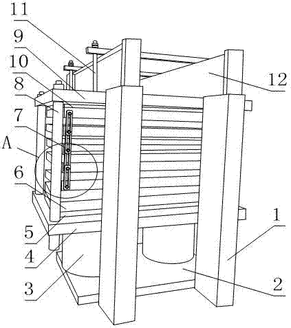
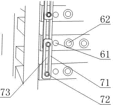
[0032] like figure 1 and figure 2 As shown, a thermoforming device includes a frame and a press plate 6 arranged on the frame, the press plate 6 is a plate-shaped structure with a built-in electric heating block 62, and the frame includes a stand 1 and a stand set on the stand The base plate 2 and the top plate 9 on the frame 1, the pressure plate 6 is located between the base plate 2 and the top plate 9, and the pressure plate 6 is a plurality of pieces, and the bottom plate 2 is also fixed with a jack 3 for adjusting the gap between the pressure plates 6 or the size of the compressive stress , connecting buckles 7 for limiting the maximum distance between adjacent pressing plates 6 are also provided between adjacent pressing plates 6;

[0033] The connecting buckle 7 comprises a strip-shaped buckle plate 71, a strip-shaped hole 73 is arranged on the length direction of the buckle plate 71, and two connecting bolts 72 are arranged in the strip-shaped hole 73, and the two co...

Embodiment 2

[0039] The present embodiment is further limited on the basis of embodiment 1, as figure 1 and figure 2 As shown, in order to ensure the uniformity of the stress on each point of the carbon crystal heating film during the pre-pressing process, it also includes a pressure equalizing plate 64 and a plurality of shape-keeping rods 8 parallel to each other, and the shape-keeping rods 8 are all fixed on the top plate 9 , the said pressure equalizing plate 64 is provided with through holes equal in number to the number of shape maintaining rods 8, said through holes are clearance fit with one shape maintaining rod 8 respectively, and the pressing plate 6 at the lowermost end is fixed on the top of the pressure equalizing plate 64 On the surface, the jack 3 acts on the lower surface of the pressure equalizing plate 64, and the shape maintaining rod 8 and the piston rod of the jack 3 are parallel to each other. In the above structure, the shape retaining rod 8 defines the angle betw...

Embodiment 3

[0043] This embodiment is further limited on the basis of any one of the above embodiments, such as figure 1 and figure 2 As shown, in order to facilitate the uniformity of the temperature values ​​at each point of each pressing plate 6, the pressing plates 6 are all copper plates, so that the carbon crystal heating film is separated from the pressing plate 6 after pre-pressing or the pressing plate 6 and the carbon crystal heating film are lowered quickly. temperature, each platen 6 is provided with a cooling medium channel 61 . The provided cooling medium channel 61 is used for passing cold fluid to take away the heat in the platen 6 .

[0044] In order to facilitate heat transfer from the electric heating block 62 to the pressing plate 6 , fins are provided on the outer side of the metal sleeve.


PUM


Abstract

The invention discloses a thermoforming device. The device comprises a rack and a plurality of pressing plates which are arranged on the rack, wherein the pressing plates are of plate-like structures in which electric heating blocks are built; the rack comprises a vertical frame, a bottom plate and a top plate; the bottom plate is also fixedly provided with a jack; a connecting buckle is also arranged between adjacent pressing plates; the connecting buckles comprise strip-shaped buckling plates; the buckling plates are provided with strip-shaped holes; two connecting bolts are arranged in the strip-shaped holes; the upper end of the vertical frame is also provided with a cross beam; the cross beam is also provided with a threaded rod; the pressing plates are also provided with a plurality of mounting holes; at least one electric heating block is arranged in the mounting holes; each electric heating block comprises a metal casing, a plurality of porcelain bushings and an electric heating rod; the two ends of the metal casing are also in threaded connection with caps. The device has a simple structure; the temperature of each point of a balance press plate is conveniently balanced, the service life is long, and the machining efficiency and the machining quality of a pre-pressing forming process in a carbon crystal heating film manufacturing process are favorably improved.

Description

technical field [0001] The invention relates to the field of carbon crystal film production equipment, in particular to a hot pressing forming device. Background technique [0002] Carbon crystal, the full name of carbon microcrystal, is a crystal structure of carbon. The chemical properties of elemental carbon are relatively stable at room temperature, insoluble in water, dilute acids, dilute alkalis and organic solvents. Carbon crystals and their compounds are widely used in industrial high-tech and medical high-tech. The carbon in carbon crystal film The crystal composite layer contains carbon nanotubes, modified ball-milled short carbon fibers, resin coatings and infrared emitting powders, which have good anti-oxidation, fresh-keeping and heat insulation effects, and have strong far-infrared radiation, high electrothermal conversion efficiency, It has the characteristics of small surface temperature difference, good corrosion resistance, weather resistance and aging...

Claims


Application Information

Patent Timeline
Patent Type & Authority Applications(China)
IPC IPC(8): B30B9/00B30B15/00B30B15/34
Inventor 李杨忠
Owner CHENGDU YANGZHONG NEW ENERGY TECH
Learn More