Method for eliminating stray light of fundus camera

A stray light and camera technology, applied in ophthalmoscopes, eye testing equipment, medical science, etc., can solve problems such as complex calculations of the system

Inactive Publication Date: 2015-07-08
宁波奉化科创科技服务有限公司
View PDF7 Cites 7 Cited by
  • Summary
  • Abstract
  • Description
  • Claims
  • Application Information

AI Technical Summary

Problems solved by technology

Most of the currently existing fundus cameras use the method of setting a black spot plate at a suitable position in t...

Method used


Image

  • Method for eliminating stray light of fundus camera
  • Method for eliminating stray light of fundus camera
  • Method for eliminating stray light of fundus camera

Examples


Embodiment

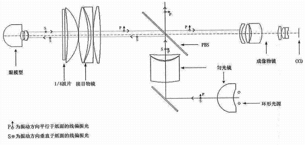
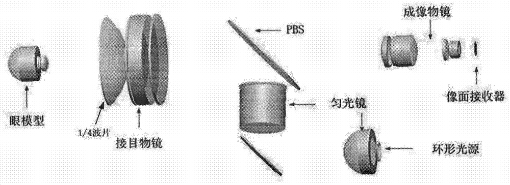
[0013] The method for eliminating the stray light of the fundus camera disclosed in this embodiment adopts a new method to eliminate the backlight reflection of the objective lens, figure 2 A schematic diagram of light propagation for an imaging system and an illumination system based on a mechanical focusing method is given. As shown in the figure, a polarizing beamsplitter prism (PBS) is added between the eyepiece objective lens and the imaging objective lens instead of a half mirror, and a 1 / 4 wave plate is added between the eyepiece objective lens and the eye. After the light emitted by the light source passes through the polarizing beam splitter, the linearly polarized light of the vertical component is reflected and then passes through the eye lens, the 1 / 4 wave plate and then enters the eye. The light reflected by the fundus passes through the 1 / 4 wave plate and the eyepiece objective lens, and then transmits to the imaging objective lens through the polarization beam ...


PUM


Abstract

The invention provides a method for eliminating stray light of a fundus camera. A polarized beam splitter (PBS) is additionally arranged between an eye object lens and an imaging object lens to replace a half-reflecting and half-transmitting mirror, and a quarter-wave plate is additionally arranged between the eye object lens and the eyes. After light emitted by a light source passes through the PBS, linearly-polarized light of vertical components is reflected, passes through the eye objects lens and the quarter-wave plate in sequence and then enters the eyes, and light reflected by the fundi passes through the quarter-wave plate and the eye object lens and then is transmitted to the imaging lens by the PBS. A new method is adopted for suppression, and LightTools software is adopted for simulation; as is verified, after the PBS and the quarter-wave plate are additionally arranged, more than 99.5% of stray light generated by the eye object lens is eliminated, and the stray light suppression effect is obvious.

Description

technical field [0001] The invention relates to a method for eliminating stray light in a fundus camera, belonging to the technical field of medical fundus imaging. Background technique [0002] Stray light refers to all abnormal light that enters the imaging system and affects the imaging quality. For the design of the fundus camera, the stray light mainly comes from the backlight reflection of the cornea of ​​the eye. Due to the high reflectivity of the cornea, the backlight reflection of the cornea will introduce a lot of stray light to the imaging system. If good suppression measures cannot be taken, the imaging light reflected by the retina will be lost in the stray light, seriously affecting the imaging system. image quality. Such as figure 1 , because the cornea has a certain curvature, the light incident on the center of the cornea will enter the imaging system after being reflected by the cornea, while the light incident on the edge of the cornea will leave the i...

Claims


Application Information

Patent Timeline
IPC IPC(8): A61B3/15A61B3/12
Inventor 励彩玲
Owner 宁波奉化科创科技服务有限公司
Why Eureka
Try Eureka