
Cage rotor and bar comprising a notch

A cage-type rotor and notch technology, which is applied in the field of manufacturing cage-type rotors and rods of cage-type rotors, can solve problems such as rising contact resistance and achieve the effect of small wear

Active Publication Date: 2015-07-01
SIEMENS AG
View PDF6 Cites 1 Cited by
  • Summary
  • Abstract
  • Description
  • Claims
  • Application Information

AI Technical Summary

Problems solved by technology

Therefore overcome the problem that the contact resistance between the shorting ring and the rod increases when the rod cannot follow the movement of the shorting ring which shrinks during cooling

Method used


Image

  • Cage rotor and bar comprising a notch
  • Cage rotor and bar comprising a notch
  • Cage rotor and bar comprising a notch

Examples


Embodiment Construction

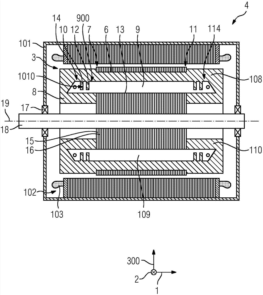
[0070] figure 1 A first embodiment of an electric machine 4 is shown, comprising a first embodiment of a cage rotor 3 . The electric machine 4 is an asynchronous machine and has a housing 101 in which a stator 102 is arranged. The stator 102 has a winding 103 . The cage rotor 3 is fastened on a shaft 18 , which is mounted rotatably about an axis of rotation in the housing 101 via rolling bearings 17 . The cage-type rotor 3 comprises a rotor stack 5 with slots 6, a short-circuit ring 8 cast at an axial end 7 of the rotor stack 5, and a rod 9 and a rod end 14 arranged in the slot 6, The short-circuit ring has a first material 108 . The rotor stack 5 comprises laminations, which are arranged in a stacked manner from an axial end 7 of the rotor stack 5 towards the other axial end 11 of the rotor stack 5 . The rotor stack 5 has, for example, a lamination 15 and a further lamination 16 at the axial end 7 . The rod end 14 can be bent through the recess 10 , wherein the recess 10...


PUM


Abstract

The rotor (3) has a short-circuit ring (8) cast at an axial end (7) of a rotor laminated core. A bar (9) is arranged in a groove (6) of the core. A bar end (14) is bendable by a notch (10). The notch includes a cut surface (1010) with the bar end. The bar end has an intense bending by the notch than a bar section, which is arranged within the groove. The notch is extended at a front surface in a direction, which includes a largest vectorial component in a bar direction (2) according to amount. The bar includes a connecting device at the notch. An independent claim is also included for a method for manufacturing a cage rotor.

Description

technical field [0001] The invention relates to a cage rotor according to the preamble of claim 1 , an electric machine comprising a cage rotor and a rod for a cage rotor. Furthermore, the invention also relates to a method for producing a cage rotor. Background technique [0002] A cage rotor of this type is known from WO 2012 / 041943 A2. Measures for improving the quality of the cage rotor and of the asynchronous machine are described here in order to overcome or reduce the problems that arise here. It is described there that the cage rotor of an asynchronous machine has rods in the rotor stack, wherein the rods can be tilted in a tilted position. Advantageously, the rod can be tilted in such a way that its end can be tilted towards the axis of the cage rotor. As a result, gaps are created in the end regions of the combined rotor laminations towards the rods, wherein the rods can be bent in the direction of the gaps. That is to say, the play enables bending of the end o...

Claims


Application Information

Patent Timeline
Patent Type & Authority Applications(China)
IPC IPC(8): H02K17/16
CPCH02K17/165H02K17/20H02K17/16H02K15/0012
Inventor 康拉德·布兰德尔马克西米利安·普法勒帕特里克·彼得罗夫斯基安德烈·特雷佩尔克里斯蒂安·德格西格弗里德·菲希特纳
Owner SIEMENS AG
Learn More