Pre-heating device for a fuel injection system

A technology of fuel injection system and preheating device, which is applied in the direction of fuel injection device, fuel heat treatment device, special fuel injection device, etc. It can solve the problems of a large amount of electric energy and time, and achieve the effect of high corrosion risk

Inactive Publication Date: 2015-07-01
MAHLE INT GMBH
View PDF11 Cites 2 Cited by
  • Summary
  • Abstract
  • Description
  • Claims
  • Application Information

AI Technical Summary

Problems solved by technology

This requires a large amount of power and time

Method used


Image

  • Pre-heating device for a fuel injection system
  • Pre-heating device for a fuel injection system
  • Pre-heating device for a fuel injection system

Examples


Embodiment Construction

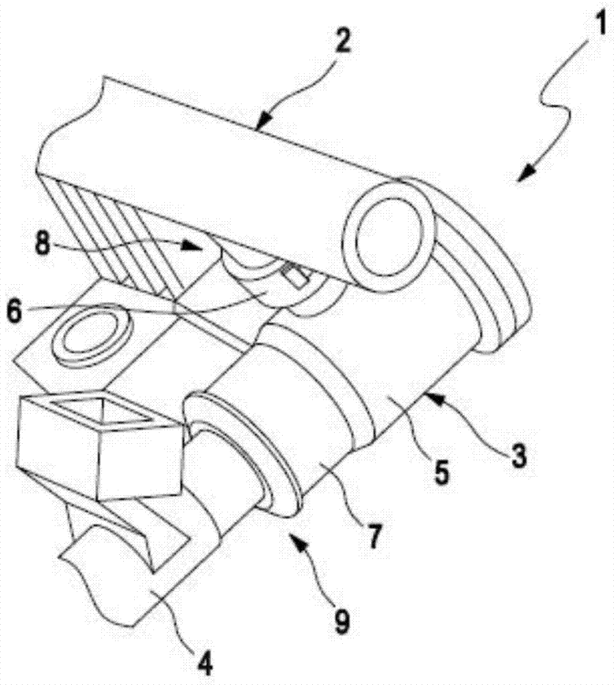
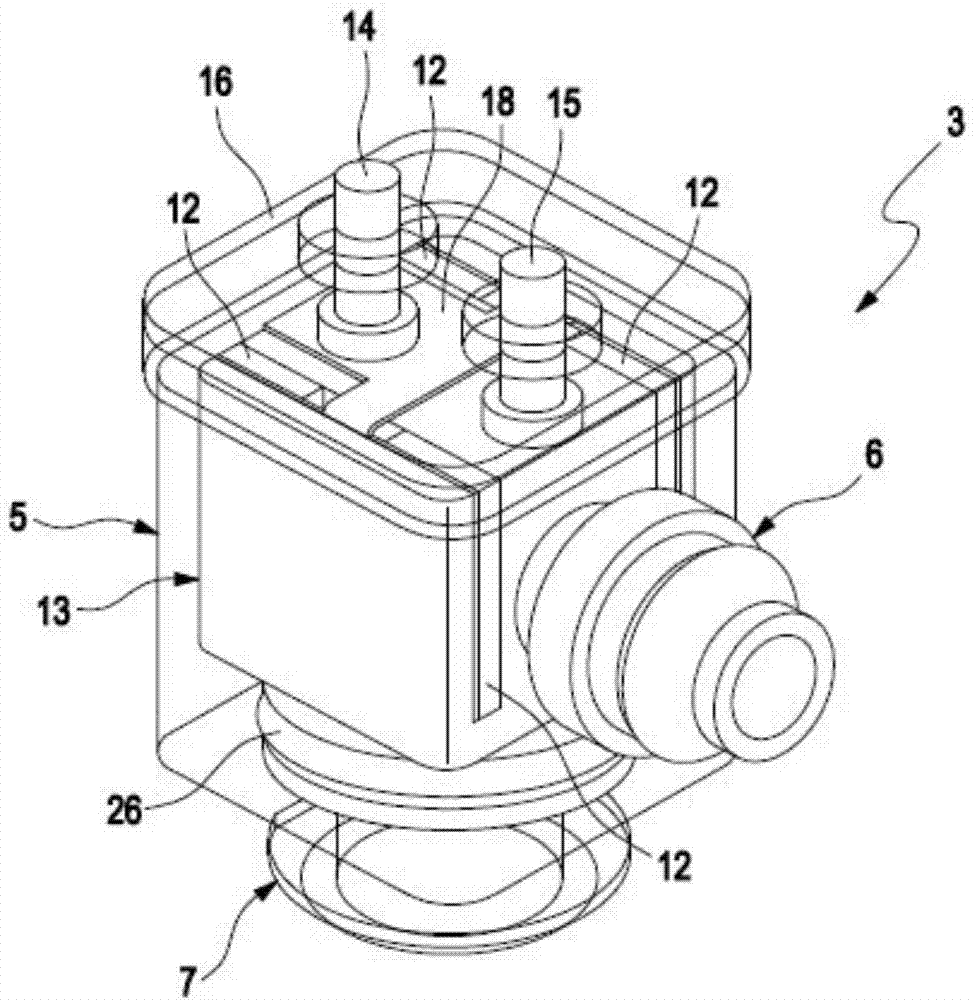
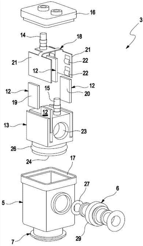
[0052] according to figure 1 , the fuel injection system 1 includes at least one distributor rail 2, several preheating devices 3 and several fuel injectors 4, and the fuel injection system 1 is used in an internal combustion engine (not shown) to supply fuel to the combustion chamber of the internal combustion engine . The distributor rail 2 is used for supplying liquid fuel, and may also be called "rail" or "common rail". Each preheating device 3 is used to preheat fuel before the fuel reaches each fuel injector 4 . For this purpose, a preheating device 3 is fluidly arranged between the distributor rail 2 and the individual fuel injectors 4 . The preheating device 3 thus comprises a housing 5 which has an inlet connection 6 via which the preheating device 3 can be directly connected to the distributor rail 2 . Furthermore, the housing 5 has an outlet connection 7 via which the individual fuel injectors 4 can be directly connected to the individual preheating devices 3 . ...


PUM


Abstract

The present invention relates to a pre-heating device (3) for pre-heating fuel of an internal combustion engine, comprising an inlet port (6) for connecting the pre-heating device (3) to a distributor strip (2) of a fuel injection system (1) of the internal combustion engine, an outlet port (7) for connecting a fuel injector (4) of the fuel injection system (1) to the pre-heating device (3), a pre-heating chamber (10) that can be flown through by the fuel and is fluidically connected to the inlet port (6) and the outlet port (7), and comprising at least one electrical heating element (12) for heating the fuel in the pre-heating chamber (10). A particularly efficient heat transfer can be achieved with at least one metallic heating body (13) which is exposed in the pre-heating chamber (10) to the fuel and in which the at least one heating element (12) is introduced.

Description

technical field [0001] The invention relates to a preheating device for a fuel injection system of an internal combustion engine, which is arranged in particular in a motor vehicle. The invention also relates to a fuel injection system for an internal combustion engine equipped with at least one preheating device as described. Background technique [0002] In fuel-driven internal combustion engines, which have a high viscosity at low temperatures, there is the problem that the use of such fuels does not create an ignitable mixture in the combustion chamber of the internal combustion engine, which is used to start the internal combustion engine, i.e. for use in these Starting the internal combustion engine at low temperatures. In so-called "biofuels", especially biodiesel, this problem tends to occur at temperatures below +14°C. Other biofuels, such as ethanol and methanol, are characterized by a flash point of about 12°C, which is very high compared to the flash point of c...

Claims


Application Information

Patent Timeline
Patent Type & Authority Applications(China)
IPC IPC(8): F02M51/00F02M53/02F02M53/06F02M69/46F02M63/02F02M31/125
CPCF02M53/02F02M2200/95F02M51/005F02M2200/80F02M69/465F02M53/06F02M2200/60F02M63/0225F02M31/125Y02T10/12
Inventor 塔德乌·阿马拉尔罗伯塔·克鲁斯费尔南多·约施诺法比奥·莫雷拉于尔根·施特林帕特里克·克林巴彻维尔纳·谢德勒马里奥·韦茨尔
Owner MAHLE INT GMBH
Why Eureka
Try Eureka