
Organic light-emitting element

A technology for organic light-emitting elements and light-emitting elements, applied in organic semiconductor devices, electrical components, optics, etc., can solve the problem of not simultaneously solving the problems of luminous efficiency and chromaticity

Inactive Publication Date: 2015-07-01
TORAY ADVANCED MATERIALS RES LAB CHINA
View PDF10 Cites 11 Cited by
  • Summary
  • Abstract
  • Description
  • Claims
  • Application Information

AI Technical Summary

Problems solved by technology

[0016] As mentioned above, the prior art uses amine derivatives with a specific structure with a high refractive index and materials that meet specific parameters to improve the light extraction efficiency and chromaticity as the material of the organic cover layer, but the luminous efficiency and chromaticity have not been solved at the same time. problems, especially in blue light-emitting elements

Method used


Image

  • Organic light-emitting element
  • Organic light-emitting element
  • Organic light-emitting element

Examples


Embodiment 1

[0227] After the alkali-free glass is ultrasonically cleaned in isopropanol for 15 minutes, it is subjected to UV ozone cleaning treatment in the atmosphere for 30 minutes. Using the vacuum evaporation method, first evaporate aluminum 100nm to make the anode, then on the anode hole injection layer (NPD and F4-TCNQ (weight ratio 97:3), 50nm), hole transport layer (NPD, 80nm), blue Emitting layer (BH and BD (weight ratio 97:3, 20nm), electron transport layer (Alq 3 , 30nm), the electron injection layer (LiF, 1nm) was sequentially stacked and evaporated, and Mg and Ag (weight ratio 10:1, 15nm) were co-evaporated to make a semi-transparent cathode.

[0228] The compounds used above are shown below.

[0229]

[0230]

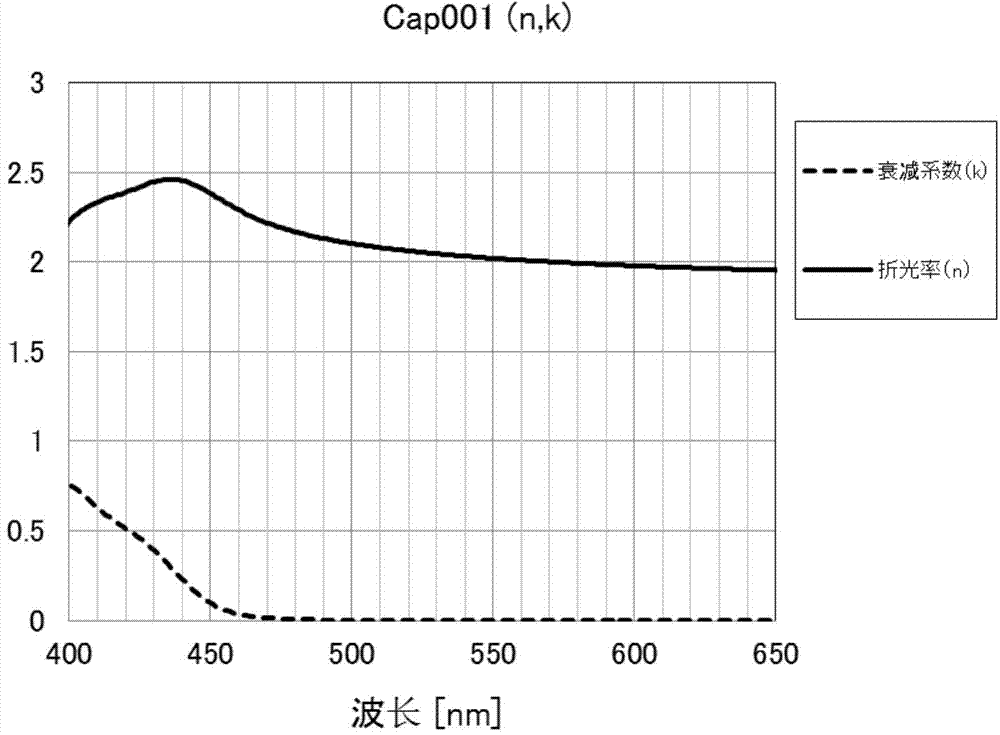
[0231] Cap001 (60nm) was then evaporated as a capping layer.

[0232] Finally, in a glove box in a dry nitrogen atmosphere, seal the light-emitting element with a sealing plate made of non-alkali glass with an epoxy resin adhesive.

[0233] The luminance and...

Embodiment 2

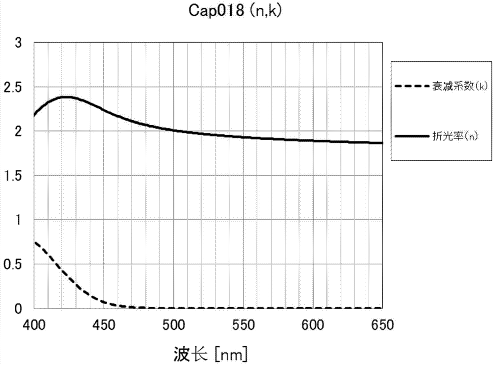
[0236] Except that the material of the covering layer is Cap018, the rest are the same as that of Example 1.

[0237] An organic light-emitting element was evaluated. See Table 2 for the evaluation results.

Embodiment 3

[0239] Except that the material of the cover layer is Cap039, the rest are the same as that of Example 1.

[0240] An organic light-emitting element was evaluated. See Table 2 for the evaluation results.


PUM


Abstract

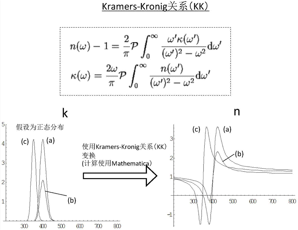
An organic light-emitting element, including a substrate, a first electrode, a light-emitting layer containing more than one organic layer film, and a light-emitting element of a second electrode. The light-emitting element is provided with a covering layer. In a wavelength range of 430 nm - 460 nm, at least one point of the attenuation coefficient of an organic material contained in the covering layer is greater than 0.10, and in a wavelength range of 460 nm - 500 nm, the attenuation coefficient is below 0.10. The organic light-emitting element achieves high light-emitting efficiency and color reproducibility, and can be used as a backlight source or illumination for an organic EL display or a liquid crystal display, or as a light source, indication board or identification lamp etc. for devices such as meters.

Description

technical field [0001] The present invention relates to an organic light-emitting element, especially an organic light-emitting element with greatly improved light extraction efficiency. Background technique [0002] An organic light-emitting element is a self-luminous display device, which has the characteristics of thinness, wide viewing angle, low driving voltage, and high-brightness luminescence. [0003] Generally, the principle of light emission of an organic light-emitting element is that holes and electrons injected by the electrodes recombine in the light-emitting layer and transition from an excited state to a ground state to generate light. The device is characterized by its thin shape, high luminance at low driving voltage, and various colors of light by selecting different light-emitting materials, so it has attracted much attention. [0004] Since C.W.Tang of Kodak Company revealed the high-brightness luminescence of organic thin-film components, extensive res...

Claims


Application Information

Patent Timeline
Patent Type & Authority Applications(China)
IPC IPC(8): H01L51/52H01L51/54
CPCH01L51/52G02F1/133602H10K50/82H10K50/818H10K50/858H10K85/615H10K50/844H10K85/626H10K85/633H10K85/636H10K85/6572H10K85/622H10K85/653H10K85/654H10K85/655
Inventor 金光男王鹏石垣刚田中大作池田武史西山卓哉
Owner TORAY ADVANCED MATERIALS RES LAB CHINA
Learn More