Eureka AIR delivers breakthrough ideas for toughest innovation challenges, trusted by R&D personnel around the world.

Coupling staged combustion and smoke recirculation low NOx chain grate furnace

A flue gas recirculation and staged combustion technology, applied in the field of low NOx chain furnaces and chain furnaces, can solve the problems of inability to achieve high efficiency and low emission, high emissions of chain furnaces, achieve good ignition, stable combustion, burnout, reduce combustion temperature and combustion. the effect of strength

Active Publication Date: 2015-07-01
江苏朗润环保科技有限公司
View PDF7 Cites 18 Cited by
  • Summary
  • Abstract
  • Description
  • Claims
  • Application Information

AI Technical Summary

Problems solved by technology

[0004] The purpose of the present invention is in order to solve the chain furnace NO that background technology mentions x Emissions are high but existing technologies cannot achieve high efficiency and low NO x Combustion issues, thus providing a low NO x chain furnace

Method used


Image

  • Coupling staged combustion and smoke recirculation low NOx chain grate furnace
  • Coupling staged combustion and smoke recirculation low NOx chain grate furnace

Examples


Embodiment approach 1

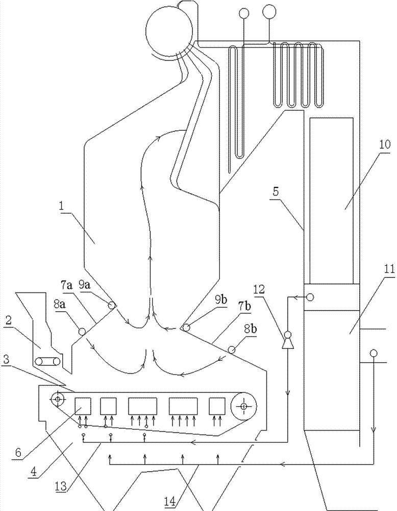
[0023] to combine figure 1 Describe this embodiment, the coupling staged combustion and flue gas recirculation of the present invention with low NO x Chain furnace, the chain furnace is composed of furnace 1, coal feeder 2, chain grate 3, slag hopper 4 and tail flue 5; the furnace 1 is divided into upper and lower parts by front furnace arch 7a and rear furnace arch 7b; An economizer 10 and an air preheater 11 are arranged from top to bottom in the tail flue 5; a plurality of primary air chambers 6 are arranged in the space area wrapped by the chain grate 3, and a plurality of primary air chambers 6 are arranged along the The direction of travel of the chain grate 3 (from left to right) is arranged in a "one" shape, and the outlets of the multiple primary air chambers 6 communicate with the chain grate 3 to supply the chain grate. 3 The primary air 14 required for the combustion of the upper coal seam; a plurality of front wall secondary air nozzles 8a and a plurality of rea...

Embodiment approach 2

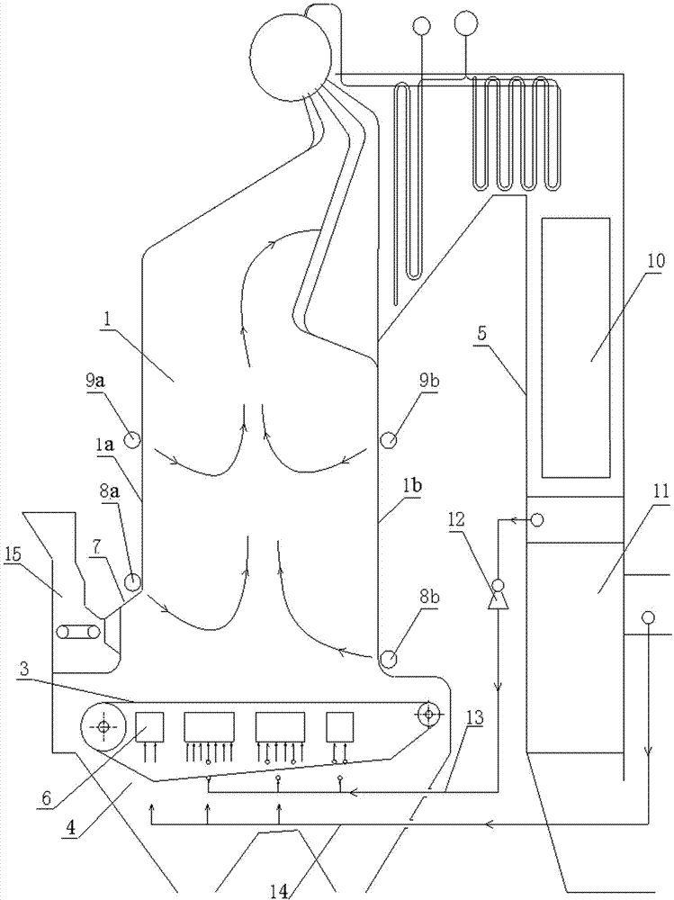
[0029] to combine figure 2 To illustrate this embodiment, the present invention couples air classification and flue gas recirculation to low NO x The chain furnace can also be equipped with an inverted coal thrower grate. The chain furnace is composed of a furnace 1, a coal feeder 15, a chain grate 3, a slag hopper 4 and a tail flue 5. The coal particles are formed by the coal feeder. The coal machine 15 is thrown to the right end of the chain grate 3, and the chain grate 3 is reversed from right to left; the furnace 1 is provided with a front wall 1a and a rear wall 1b, and the root of the front wall 1a has A small front furnace arch 7; an economizer 10 and an air preheater 11 are arranged from top to bottom in the tail flue 5; a plurality of primary air chambers 6 are arranged in the space area wrapped by the chain grate 3, A plurality of primary air chambers 6 are arranged in a "one" shape along the direction of travel of the chain grate 3 (from right to left) and communi...


PUM


Abstract

The invention discloses a coupling staged combustion and smoke recirculation low NOx chain grate furnace. The chain grate furnace is composed of a hearth, a coal feeder, a chain grate stoker, a slag hopper and a tail flue. The hearth is divided into an upper hearth part and a lower hearth part through a front furnace arch and a rear furnace arch. Secondary air and over fire air are arranged in a suspension combustion area of the lower hearth body to organize staged combustion in the suspension combustion area, the secondary air of the lower hearth body is fed through secondary air spraying ports in the lower areas of the front furnace arch and the rear furnace arch, the over fire air is fed through over fire air spraying ports in the intersection of the upper hearth body and the lower hearth body, primary air is fed in a segmented mode below the stoker so as to organize the staged combustion of a stocker combustion area, low-temperature furnace smoke is extracted from the tail flue to be fed to the bottom of the stoker through a recirculation draught fan to perform recirculation, coal particles in the furnace are in the state far away from the stoichiometric ratio combustion state for a long time through two-layer staged combustion of the stocker combustion area and the suspension combustion area and smoke recirculation of the stoker combustion area, and efficient and low NOx combustion of the chain grate furnace is achieved.

Description

technical field [0001] The invention relates to a chain furnace, in particular to a low NOx chain furnace coupled with staged combustion and flue gas recirculation, and belongs to the technical field of industrial boiler combustion. Background technique [0002] Among the large number of coal-fired industrial boilers in my country at present, chain furnaces account for more than 60% of the market share. In terms of combustion organization, the chain furnace is dominated by constant-speed moving grate layer combustion, supplemented by suspended combustion formed by fine particles in the upper area of ​​the grate. Correspondingly, the air distribution is dominated by the primary air sent from the bottom of the grate, and the secondary air is supplemented by the front and back arches on the upper part of the grate (used to supply the air required for the suspended combustion zone and to adjust the combustion); The coal seam goes through several stages of preheating and drying,...

Claims


Application Information

Patent Timeline
Patent Type & Authority Applications(China)
IPC IPC(8): F23B30/08F23B80/02F23L1/00F23L9/00
CPCY02E20/34
Inventor 凌忠钱况敏
Owner 江苏朗润环保科技有限公司
Why Eureka
Eureka Blog
Learn More