
Indoor positioning device and positioning method

A technology for indoor positioning and to-be-located points, applied in electrical components, wireless communication and other directions, can solve the problems of inability to accurately measure the distance between nodes, large positioning error, wireless signal influence, etc., to achieve novel positioning methods, simple device structure, good stability

Active Publication Date: 2015-06-24
SHENZHEN INST OF ADVANCED TECH CHINESE ACAD OF SCI
View PDF6 Cites 9 Cited by
  • Summary
  • Abstract
  • Description
  • Claims
  • Application Information

AI Technical Summary

Problems solved by technology

[0004] The patent application number CN201110054768.3 proposes a weighted trilateration positioning method based on RSSI. The limitation is that this method cannot accurately measure the distance between nodes, resulting in a large positioning error
[0005] The patent application number CN201210290193.X proposes a WLAN indoor positioning method based on matrix correlation. The limitation is that collecting indoor environmental feature fingerprints requires a lot of manpower and material resources, and due to the complex indoor environment and obvious multipath effects, wireless signals are easily affected. Positioning accuracy is not high

Method used


Image

  • Indoor positioning device and positioning method
  • Indoor positioning device and positioning method
  • Indoor positioning device and positioning method

Examples


Embodiment Construction

[0029] In order to make the object, technical solution and advantages of the present invention clearer, the present invention will be further described in detail below in conjunction with the accompanying drawings and embodiments. It should be understood that the specific embodiments described here are only used to explain the present invention, not to limit the present invention.

[0030] The specific realization of the present invention is described in detail below in conjunction with specific embodiment:

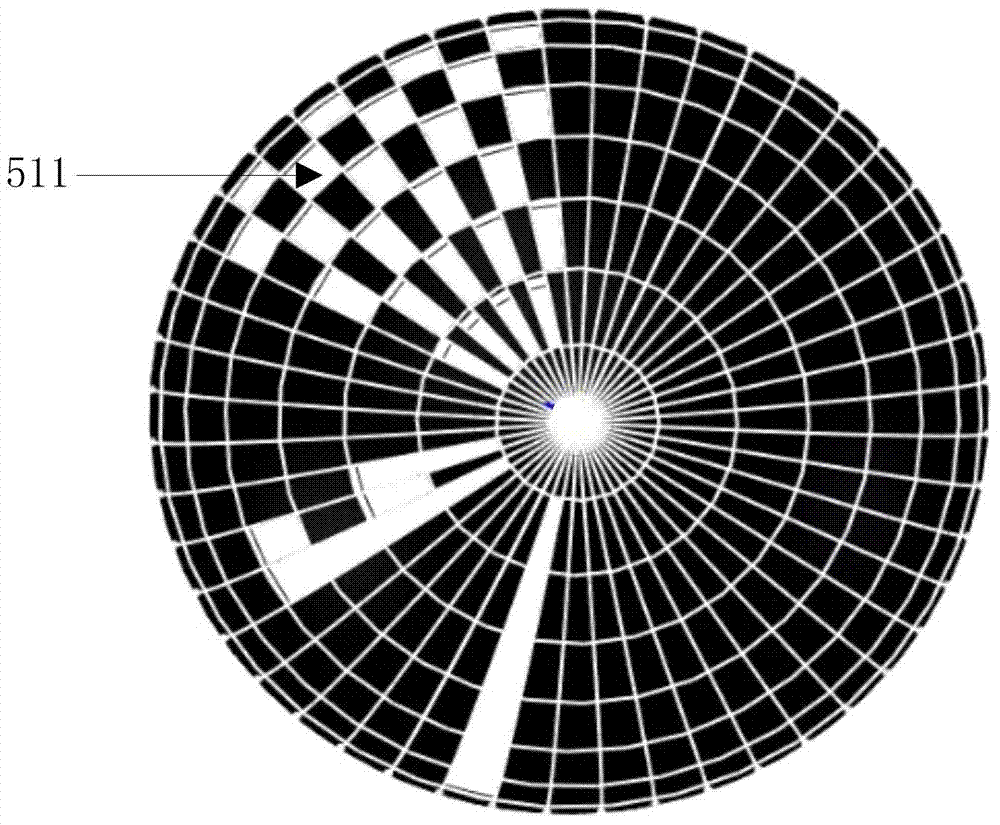
[0031] Please refer to Figure 1~3 The embodiment of the present invention provides an indoor positioning device, which has the following structure: it includes a base 1, a light source 2 arranged on the base 1, a rotating member 3, and a drive motor for driving the rotating member 3 to rotate at a uniform speed in one direction 4. The rotating housing 5 fixed on the rotating member 3 and rotating with the rotating member 3 , and the controller 6 for controlling the freq...


PUM


Abstract

The invention is suitable for the technical field of positioning, and provides an indoor positioning device. The positioning device comprises a base and a light source, a rotation piece, a driving motor, a rotation shell and a controller which are arranged on the base; the light source is located on the center of an opening of the rotation shell; the rotation shell is divided into multiple coding circles in the latitude direction, each coding circle is divided into multiple coding bits in the longitude direction, two or more successive non-light-transmitting coding bits do not exist in each circle, and a start bit and a stop bit are formed by multiple coding bits configured in a particular mode; the configuration of the coding bits of different coding circles is different; an optical coupler with a card slot is arranged on the base, the rotation piece is provided with a light-blocking sheet, the light-blocking sheet penetrates through the card slot once, and one time of frequency jump of the light source occurs; the positioning device further comprises a receiving end used for inducting optical signals and frequency jump and performing positioning. According to the indoor positioning device and the positioning method, the rotation shell and the jump light source are combined with the receiving end to be used for inducting the optical signals and achieving positioning, and the structure is simple and concise; the positioning method is novel, accurate, good in stability and low in cost, and is suitable for indoor highly-precise positioning.

Description

technical field [0001] The invention belongs to the technical field of positioning, and in particular relates to an indoor positioning device and a positioning method. Background technique [0002] With the advancement of science and technology and the development of social economy, people's demand for indoor positioning services is increasing day by day. In some public places, such as shopping malls, airports, exhibition halls, office buildings, warehouses, underground parking lots, etc., accurate indoor positioning information can be convenient for users. Shopping, traveling, finding indoor targets, etc.; able to efficiently manage available space and inventory materials; able to navigate police, firefighters, soldiers, and medical staff to complete specific indoor tasks. Smart spaces and ubiquitous computing are inseparable from location-based services, so indoor positioning has broad application prospects. Although GPS can meet the needs of many applications in outdoor ...

Claims


Application Information

Patent Timeline
IPC IPC(8): H04W64/00
CPCH04W64/00
Inventor 谭光谢波毛成华肖钟凯
Owner SHENZHEN INST OF ADVANCED TECH CHINESE ACAD OF SCI
Learn More