
Current sharing control system and method

A flow control system and flow control technology, applied in electric vehicles, electrical components, load supply circuits, etc., can solve problems such as high design power of control circuits, inability to maintain consistent battery capacity in parallel, affecting battery life and stability, etc. To achieve the effect of improving stability and service life

Inactive Publication Date: 2015-06-24
GUANGXI POWER GRID CORP +1
View PDF3 Cites 4 Cited by
  • Summary
  • Abstract
  • Description
  • Claims
  • Application Information

AI Technical Summary

Problems solved by technology

However, due to the self-consumption during battery manufacturing and actual use, the capacity of parallel batteries cannot be kept consistent. When one or several of them have undervoltage protection, the remaining batteries need to bear the current required to load all the loads. Excessive discharge current will affect the service life and stability of the battery, and will inevitably lead to a large design power of the control circuit, increasing heat dissipation problems and design difficulties

Method used


Image

  • Current sharing control system and method
  • Current sharing control system and method
  • Current sharing control system and method

Examples


Embodiment Construction

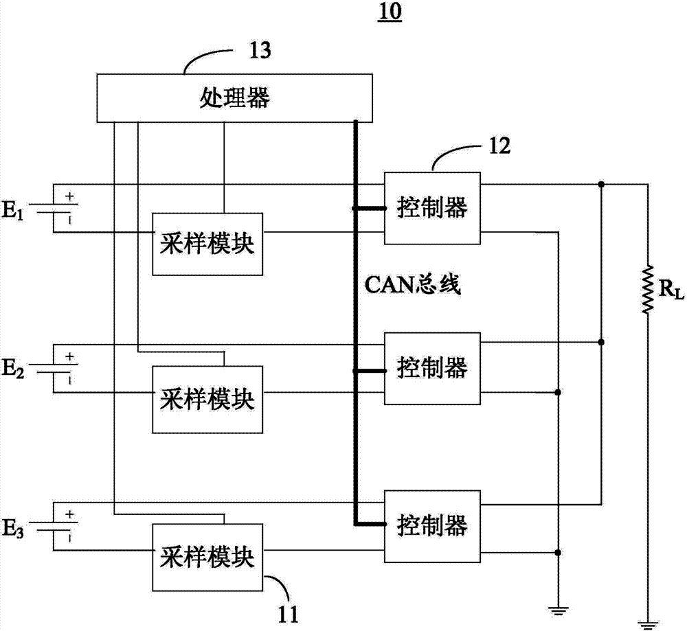
[0024] see figure 2 , figure 2 is a schematic structural diagram of the current sharing control system according to the first embodiment of the present invention. Such as figure 2 As shown, the current sharing control system 10 is used to control the output current of at least two groups of power supplies connected in parallel, wherein these power supplies connected in parallel can be batteries or other energy storage elements similar to batteries, such as lithium-ion batteries, lithium polymer Batteries, lead storage batteries, nickel-cadmium batteries, nickel-hydrogen batteries, super capacitors, or future new energy storage products, etc., and the output current is the discharge current of the battery. The current sharing control system 10 of this embodiment includes: multiple sampling modules 11 , multiple controllers 12 and a processor 13 .

[0025] The processor 13 is connected to multiple sampling modules 11 and multiple controllers 12 , wherein the processor 13 p...


PUM


Abstract

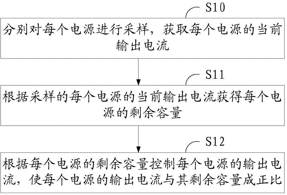
The invention discloses a current sharing control system and method. The system and method are used for controlling output currents of at least two sets of power sources which are connected in parallel. The current sharing control system comprises multiple sampling modules, multiple controllers and a processor, wherein each sampling module is connected with the corresponding power source and samples the corresponding power source to obtain the current output current, each controller is connected with the corresponding power source so as to control the output current of the corresponding power source, and the processor is connected with the sampling modules and the controllers and sends control signals to the controllers according to the remaining capacity of each power source so that the output currents of all the power sources can be controlled through the controllers, and therefore the output currents of all the power sources are in direct proportion to the remaining capacities. In this way, the output currents of the parallel power sources can be adjusted in real time, the remaining capacities of all the power sources can be zero at the same time, when some power sources are damaged, the power supply of other power sources can not be affected, the stability of a power supply system with the parallel power sources can be improved, and the service life of the power supply system with the parallel power sources can be prolonged.

Description

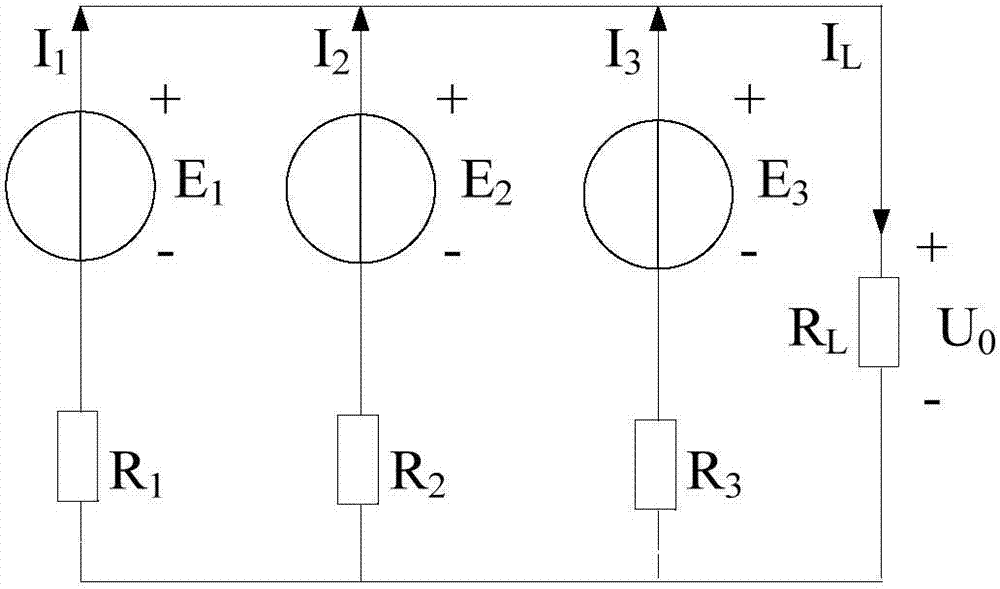
technical field [0001] The invention relates to the technical field of battery application, in particular to a current equalization control system and method. Background technique [0002] In order to obtain a battery combination with a larger capacity, the battery is generally connected in parallel, that is, multiple batteries are connected in parallel to increase the battery capacity. However, in practical applications, if the batteries are directly connected in parallel without protection or limitation, it is easy to form a circulating current between each other, and it is easy to cause unbalanced discharge current to the load. If one of the batteries fails or even has a short circuit, it will affect the characteristics of the entire parallel battery pack. [0003] Taking lithium battery as an example, the battery parallel equivalent circuit model is as follows: figure 1 shown. If the open circuit voltage of the battery E 1 ,E 2 ,E 3 inconsistent, the total output v...

Claims


Application Information

Patent Timeline
Patent Type & Authority Applications(China)
IPC IPC(8): H02J7/00
CPCH02J7/0063
Inventor 卓伟光石大明黄秀琼高立克陈卫东
Owner GUANGXI POWER GRID CORP
Learn More