Azimuthal telescope pupil plane and image plane mechanical racemic integration device

A telescope, horizon technology, applied in telescopes, optics, instruments, etc., can solve problems such as the inability of adaptive optics to accurately detect atmospheric wavefront phase information, the inability to accurately correct the impact of atmospheric disturbance imaging quality, and the inability of telescopes to achieve resolution capabilities. , to achieve the effect of increasing the complexity of the optical structure, easy control and implementation, innovation and practicability

Active Publication Date: 2015-06-24
INST OF OPTICS & ELECTRONICS - CHINESE ACAD OF SCI
View PDF3 Cites 6 Cited by
  • Summary
  • Abstract
  • Description
  • Claims
  • Application Information

AI Technical Summary

Problems solved by technology

[0011] The technical problem to be solved by the present invention is: for the rotation of the pupil surface of the horizon telescope, the adaptive optics cannot accurately detect the phase information of the atmospheric wavefront, and thus cannot accurately correct the influence of atmospheric disturbance on the imaging quality, so that the telescope cannot reach or approach the theoretical diffraction Limit resolution ability, unable to achieve the purpose of high resolution observation

Method used


Image

  • Azimuthal telescope pupil plane and image plane mechanical racemic integration device
  • Azimuthal telescope pupil plane and image plane mechanical racemic integration device
  • Azimuthal telescope pupil plane and image plane mechanical racemic integration device

Examples


Embodiment Construction

[0040] The present invention will be further described below in conjunction with the accompanying drawings and specific embodiments.

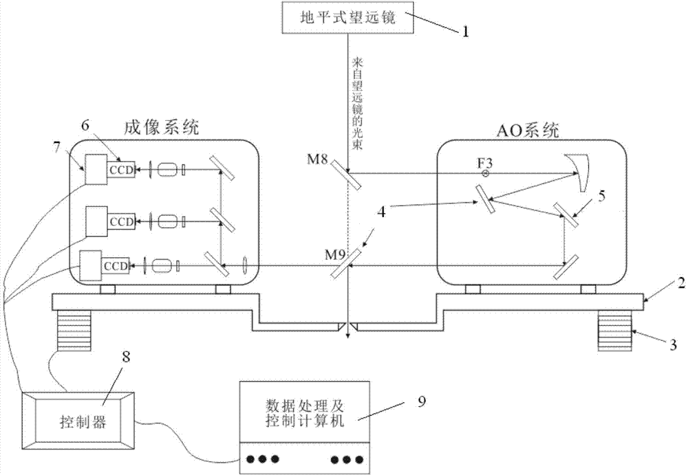
[0041] An integrated device for mechanical derotation of the pupil plane and the image plane of the horizon telescope (see figure 1 ), it is characterized in that the device includes: horizon telescope 1, turntable 2, electric control driver 3, relay optical path 4, deformable mirror DM 5, camera 6, camera rotating table 7, controller 8, data processing and control computer 9 . The turntable 2 is located below the azimuth axis, and the electronically controlled driver 3 controls the overall rotation of the turntable 2, which is mainly responsible for eliminating the pupil rotation caused by the horizon-level telescope tracking the target. There is a reflective mirror fixed on the turntable 2 at the center of rotation of the turntable 2, and its function is to reflect the light path from the azimuth axis to the relay light path 4. There is a d...


PUM


Abstract

The invention discloses an azimuthal telescope pupil plane and image plane mechanical racemic integration device comprising an azimuthal telescope, a rotating table, an electrical control drive, a relay optical path, a deformable mirror DM, a camera, a camera rotating table, a controller and a data processing and controlling computer. Owing to the mechanical advantages of an azimuthal frame, a majority of large-diameter telescopes adopt the structures currently in the worldwide. However, in the target tracking process, the pupil plane and image plane rotate accordingly, the atmospheric wavefront aberration cannot be measured and corrected accurately through adaptive optics due to pupil plane rotation, and continuous and stable observation results cannot be acquired by the telescope due to image plane rotation. According to the device, the pupil plane rotation is eliminated through the rotation table, the image plane rotation is eliminated through the rotating camera, additional instrument polarization is omitted, optical path integrated reflectivity reducing is avoided, and the practicality and creativity are high.

Description

technical field [0001] The invention relates to the technical field of a derotation device for pupil plane rotation and image plane rotation of a horizon telescope, in particular to an integrated device for mechanical derotation of the pupil plane and image plane of a horizon telescope. Background technique [0002] Due to the superior mechanical properties of the ground-level rack, with the continuous improvement of human requirements for the image resolution of the telescope, the aperture of the telescope is also increasing. Only the ground-level rack structure can meet the use requirements. The installation location of the telescope with the ground-level rack structure has nothing to do with the geographical latitude. At present, most large-aperture telescopes in the world use this structure. [0003] However, horizon-level telescopes also have some defects, such as pupil plane rotation and image plane rotation. [0004] The rotation of the pupil plane will make adaptive...

Claims


Application Information

Patent Timeline
Patent Type & Authority Applications(China)
IPC IPC(8): G02B23/16
CPCG02B23/16
Inventor 饶长辉王志勇顾乃庭饶学军朱磊李程黄金龙程云涛刘洋毅姚本溪郑联慧张兰强
Owner INST OF OPTICS & ELECTRONICS - CHINESE ACAD OF SCI
Why Eureka
Try Eureka