
Virtual array DOA estimation method based on L type array

A virtual array, DOA technology, applied to the direction or offset system, direction finder using ultrasonic/sonic/infrasonic waves, etc., can solve the problem that the array scale cannot be made very large, sub-maximum, difficult to apply, etc. question

Inactive Publication Date: 2015-06-24
CHINA JILIANG UNIV
View PDF4 Cites 41 Cited by
  • Summary
  • Abstract
  • Description
  • Claims
  • Application Information

AI Technical Summary

Problems solved by technology

Direction finding methods based on conventional beamforming scans are inherently limited, limited by the "Rayleigh criterion", and the estimated resolution depends on the array length, only when the separation angle between two sources in space is greater than the reciprocal of the array aperture , to be distinguished
In order to improve the resolution of the basic array, when the signal wavelength λ must be , generally only increase the aperture length of the basic array, that is, increase the array element m or increase the array spacing d, but increasing the number of array elements will increase the complexity and cost of the equipment, Increasing the array element spacing will cause submaximum. Due to the limitation of the actual situation, the scale of the array cannot be made very large. Therefore, it is difficult to apply in actual engineering to improve the resolution by only increasing the array aperture.

Method used


Image

  • Virtual array DOA estimation method based on L type array
  • Virtual array DOA estimation method based on L type array
  • Virtual array DOA estimation method based on L type array

Examples


Embodiment Construction

[0044] Below in conjunction with accompanying drawing and embodiment the present invention will be further described:

[0045] Step 1: Construct an L-shaped array and determine the signal model received by the array;

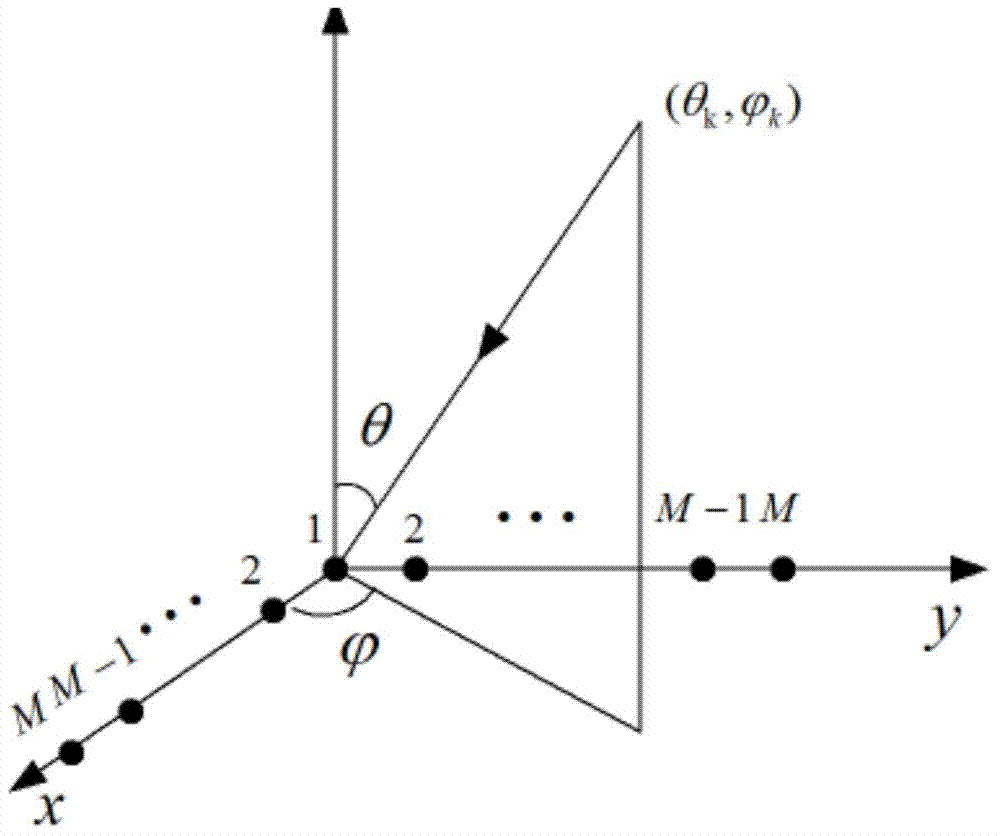
[0046] Such as figure 1 As shown, the sound pressure time domain signal is received by 2M-1 array elements in the L-shaped array. This L-shaped array consists of a uniform linear array Z with the number of array elements on the x-axis x and a uniform linear array Z with array elements M on the y-axis y Composition, wherein, 2M-1 is the number of elements of the L-shaped array, M is an integer not less than 2, and d is the distance between elements. Assuming that there are K sources incident on the array in space, the two-dimensional direction of arrival is are the elevation angle and azimuth angle of the kth signal source, respectively.

[0047] Assuming that the number of signal sources incident on the array is K, the signals received by M array elements...


PUM


Abstract

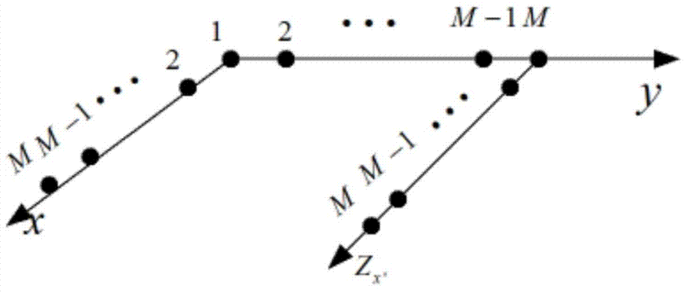
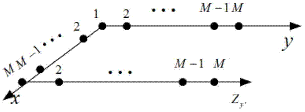
The invention discloses a virtual array DOA estimation method based on an L type array. The method comprises the steps that 1, based on the shift invariant property, a subarray Zx and a subarray Zy of the L type array horizontally shift to obtain a virtual array Zx' and a virtual array Zy', rotation invariance of two sub signals is formed due to the shift invariant property of the subarrays, and the virtual subarray signals are equal to the L type subarray Zx and L type subarray Zy input signals multiplied by a twiddle factor respectively; 2, the output of the four subarrays are combined to form a virtual array output signal Z (t); 3, the signal subspace and the noise subspace can be described by decomposing the features of covariance matrixes output by the array, mutual correlation processing is carried out on the array output signal Z(t) to obtain Rzz, and eigenvalue decomposition is carried out to obtain signal subspaces; 4, the twiddle factor is solved through linear operation, and the signal wave arrival direction can be obtained through the diagonal element of the twiddle factor. According to the virtual array DOA estimation method, no spectral function needs to be calculated, the phenomenon that the wave arrival direction is indirectly calculated without searching for the peak value is avoided, the complexity is lowered, the equipment complexity and cost are reduced, and the positioning precision is high.

Description

technical field [0001] The invention belongs to the technical field of array signal processing two-dimensional DOA estimation, and in particular relates to a virtual array element DOA estimation method based on an L-shaped array. Background technique [0002] Object Orientation Estimation (DOA) estimation is an important branch of signal processing fields such as sonar, radar, wireless communication, medical imaging, microphone array processing, etc. The basic problem solved by DOA is to determine multiple interested targets in a certain space at the same time The spatial position of the signal, that is, the direction angle at which each target signal arrives at the sensor array. Direction finding methods based on conventional beamforming scans are inherently limited, limited by the "Rayleigh criterion", and the estimated resolution depends on the array length, only when the separation angle between two sources in space is greater than the reciprocal of the array aperture ,...

Claims


Application Information

Patent Timeline
Patent Type & Authority Applications(China)
IPC IPC(8): G01S3/802
CPCG01S3/802
Inventor 王强叶虹敏袁昌明范昕炜
Owner CHINA JILIANG UNIV
Learn More