
Lorentz-force axial magnetic bearing of outer rotor

A technology of axial magnetic bearings and outer rotors, applied in the direction of shafts and bearings, bearings, mechanical equipment, etc., can solve the problems of Lorentz force magnetic bearings, such as temperature rise, difficult heat dissipation, and large coil current, to achieve favorable heat Dispersion, high structural reliability, and the effect of improving reliability

Active Publication Date: 2015-06-24
BEIJING INSTITUTE OF PETROCHEMICAL TECHNOLOGY +1
View PDF6 Cites 23 Cited by
  • Summary
  • Abstract
  • Description
  • Claims
  • Application Information

AI Technical Summary

Problems solved by technology

Due to the large air gap of the Lorentz force magnetic bearing, generally 4 ~ 6mm, the magnetic density generated by the permanent magnet in the air gap is generally 0.2 ~ 0.4T, and the suspension ampere force is proportional to the magnetic density, that is, a large current is required In order to output a certain suspension force, so the power consumption is relatively large, and the heat generated is correspondingly large
Especially when the Lorentz force magnetic bearing is used to bear the load or output the deflection torque, the coil current is larger and the heat generated is more. Excessive heat will cause the temperature of the Lorentz force magnetic bearing to rise sharply, which will easily lead to the curing of the coil. Accidents such as melting, coil insulation varnish melting and short circuit
Due to the above defects, the existing Lorentz force magnetic bearings have the disadvantages of high power consumption and difficulty in heat dissipation in the application of magnetic suspension momentum wheels and magnetic suspension gyroscopes

Method used


Image

  • Lorentz-force axial magnetic bearing of outer rotor
  • Lorentz-force axial magnetic bearing of outer rotor
  • Lorentz-force axial magnetic bearing of outer rotor

Examples


specific Embodiment approach

[0017] The preferred embodiment of the outer rotor Lorentz force axial magnetic bearing of the present invention is:

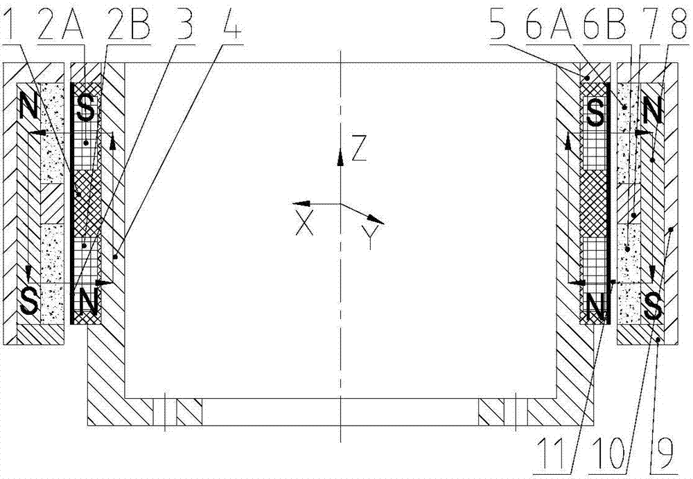
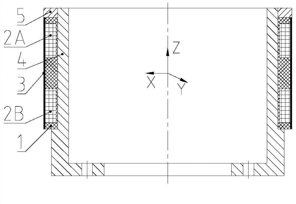
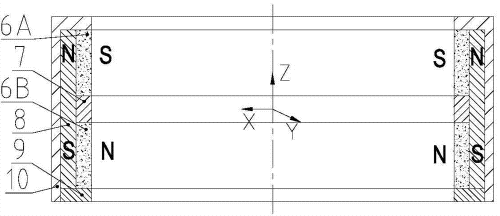
[0018] Such as figure 1 As shown, it is mainly composed of stator system and rotor system. The stator system mainly includes: skeleton 1, upper winding 2A, lower winding 2B, epoxy resin glue 3, magnetic permeable seat 4 and stator lock nut 5; the rotor system mainly includes : Upper magnetic steel 6A, lower magnetic steel 6B, magnetic isolation ring 7, magnetic conduction ring 8, rotor lock nut 9 and sleeve 10; there are two upper and lower annular grooves in the outer wall of skeleton 1, and upper winding 2A and lower winding 2B are respectively wound In the upper annular groove and the lower annular groove of the skeleton 1, and solidified on the skeleton 1 by epoxy resin glue 3, the magnetic permeable base 4 is located on the radial inner side of the skeleton 1, and the stator lock nut 5 is located on the upper end of the skeleton 1, and the skeleton 1 It ...


PUM


Abstract

The invention discloses a lorentz-force axial magnetic bearing of an outer rotor. The lorentz-force axial magnetic bearing mainly comprises two parts, namely a stator system and a rotor system, wherein the stator system mainly comprises a skeleton, an upper winding, a lower winding, epoxy resin glue, magnetic-conductive seats and a stator locking nut; the rotor system mainly comprises upper magnetic steel, lower magnetic steel, a magnetic-isolated ring, a magnetic-conductive ring, a rotor locking nut and a sleeve. The lorentz-force axial magnetic bearing disclosed by the invention has the beneficial effects that the windings are directly provided with the magnetic-conductive seats with good heat-conductive performances, so that the copper loss and the rotary loss of the windings can be quickly conducted out by the magnetic-conductive seats; since a single-edge magnetic steel structure is adopted, the lorentz-force axial magnetic bearing has the advantages of simple structure, good linearity, high bandwidth, good heat conducting performance and the like, the structure reliability of the axial magnetic bearing is improved, and simultaneously the temperature rise of the magnetic bearing is reduced, so that the lorentz-force axial magnetic bearing can be used for non-contact suspension supporting such as a magnetic suspension momentum wheel and a magnetic-suspension gyroscope.

Description

technical field [0001] The invention relates to a non-contact outer rotor Lorentz force axial magnetic bearing, in particular to an outer rotor Lorentz force axial magnetic bearing. Background technique [0002] Magnetic suspension bearings are divided into reluctance magnetic bearings and Lorentz force magnetic bearings. The former changes the magnetic density and flux at the pole surface by changing the size of the air gap or magnetomotive force, thereby controlling the magnitude and direction of the electromagnetic force. The air gap of the latter is constant, and the magnitude and direction of the ampere force in the coil are controlled by changing the magnitude and direction of the winding current. For the reluctance magnetic bearing, the magnetic density is proportional to the control current, and the electromagnetic force is proportional to the square of the magnetic density. The electromagnetic force of the reluctance magnetic bearing is proportional to the control c...

Claims


Application Information

Patent Timeline
IPC IPC(8): F16C32/04
Inventor 刘强武登云赵航樊亚洪缪存孝韩天张立元
Owner BEIJING INSTITUTE OF PETROCHEMICAL TECHNOLOGY
Learn More