
A Welding Process for Suppressing Discharge at the Tip of Solder Joints

A cutting-edge discharge and process technology, applied in manufacturing tools, welding equipment, metal processing, etc., can solve problems such as product quality not meeting requirements, inconsistent solder joint tip forms, circuit short circuits, etc., to eliminate tip phenomenon and eliminate tip discharge. , the effect of improving product quality

Inactive Publication Date: 2018-04-20
HUAIAN COLLEGE OF INFORMATION TECH
View PDF7 Cites 0 Cited by
  • Summary
  • Abstract
  • Description
  • Claims
  • Application Information

AI Technical Summary

Problems solved by technology

Sometimes even the discharge phenomenon caused by this will occur, sparks will be wiped out, and the circuit will be short-circuited.
Moreover, the tip form of the solder joints is inconsistent, and the product quality cannot meet the requirements

Method used


Image

  • A Welding Process for Suppressing Discharge at the Tip of Solder Joints

Examples


Embodiment Construction

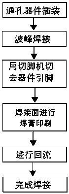
[0051] As shown in Figure 1, the present invention relates to a welding process for suppressing discharge at the tip of solder joints, which includes:

[0052] A. Through-hole component insertion:

[0053] A1) Confirm the product model, confirm the component number, confirm the component insertion method, vertical insertion, horizontal insertion, high insertion, and whether to use spacer columns, etc., to ensure the length of the component pin formation;

[0054] A2) Adjust the scale of the machine or self-made fixture;

[0055] A3) Take a component, shape it according to the requirements, insert the component into the corresponding bit number of the corresponding product board, and use a vernier caliper to check whether the length of the part of the leaking board meets the process requirements;

[0056] A4) Repeatedly adjust the scale of the machine or self-made fixtures to make the shape and length of the component pins meet the process requirements;

[0057] A5) Start bat...


PUM


Abstract

The invention discloses a welding technological process for restraining discharge of a welding spot without a point. The welding technological process for restraining the discharge of the welding spot without the point comprises the first step of plug-in mounting of dip devices, the second step of wave crest welding, the third step of device pin cutting through a pin cutter, the fourth step of welding paste printing of a welding surface, the fifth step of backflow and the sixth step of welding completion. According to the welding technological process for restraining the discharge of the welding spot without the point, the pin cutter is adopted to cut pins, so that the heights of the pins are consistent; template printing welding paste with moderate thickness is adopted, formation of a rounded welding spot is facilitated after the backflow, a suitable furnace temperature curve can be set according to different products and template thicknesses in backflow welding, and it is guaranteed that the welding spot is rounded.

Description

technical field [0001] The invention belongs to the field of welding and surface packaging technology of high-voltage electronic products, and in particular relates to a technology method for no-tip discharge of solder joints. Background technique [0002] With the development of high-voltage electronic products, it is required to reduce the tip discharge caused by device pins or solder joints as much as possible, prolong the service life of the product, and reduce the disaster and noise pollution caused by the tip discharge. At present, in the welding process, the usual solution is mainly manual trimming. No matter how careful it is, it is difficult to ensure that each solder joint is round. When connected to a high-voltage power supply, the tip can arc at high voltage, changing the performance of the board. Sometimes even the discharge phenomenon caused by this will occur, sparks will be wiped out, and the circuit will be short-circuited. Moreover, the tip form of the so...

Claims


Application Information

Patent Timeline
Patent Type & Authority Patents(China)
IPC IPC(8): B23K1/008B23K1/20H05K3/34
CPCB23K1/008B23K1/20B23K2101/36H05K3/34H05K2203/04
Inventor 李朝林刘步中魏子陵
Owner HUAIAN COLLEGE OF INFORMATION TECH
Learn More