
A display panel, its display method and display device

A display panel and display screen technology, applied in the direction of identification devices, static indicators, instruments, etc., can solve the problems of inconvenient replacement of content and poor display visual effect

Active Publication Date: 2017-05-24
BOE TECH GRP CO LTD
View PDF5 Cites 0 Cited by
  • Summary
  • Abstract
  • Description
  • Claims
  • Application Information

AI Technical Summary

Problems solved by technology

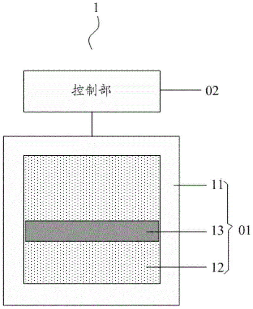
[0004] In view of this, the embodiments of the present invention provide a display panel, its display method and display device, which are used to solve the problems of inconvenient content replacement and poor visual effect of outdoor display in the daytime existing in existing billboards.

Method used


Image

  • A display panel, its display method and display device
  • A display panel, its display method and display device
  • A display panel, its display method and display device

Examples


Embodiment 1

[0080] Preferably, in the above display panel provided by the embodiment of the present invention, such as Figure 3a to Figure 3f As shown, the control part 02 includes a first electromagnet 21 and a first voltage unit 22 for supplying voltage to the first electromagnet 21 according to the display screen at the corresponding position; wherein,

[0081] Such as Figure 3a , Figure 3c and Figure 3e As shown, the first electromagnet 21 is located on the light incident side of the anti-color box 01, or as Figure 3b , Figure 3d and Figure 3f As shown, the first electromagnet 21 is located on the backlight side of the reverse color box 01;

[0082] The first voltage unit 22 is used to output the first voltage to the first electromagnet 21 when it is determined that the anti-color box 01 needs to display the color of the light incident surface of the shielding part 13 according to the display screen at the corresponding position, so that the first electromagnet The iron 2...

example 2

[0096] Preferably, in the above display panel provided by the embodiment of the present invention, the control part may also include two magnets, specifically as Figure 4a to Figure 4c As shown, the control part 02 includes a second electromagnet 31, a third electromagnet 41, a second voltage unit 32 for supplying voltage to the second electromagnet 31 according to the display screen at the corresponding position, and a second voltage unit 32 for The display screen of the third voltage unit 42 that provides voltage to the third electromagnet 41; wherein,

[0097] The second electromagnet 31 is positioned at the light incident side or the backlight side of the reverse color box 01, and the third electromagnet 41 is positioned at the backlight side or the light incident side of the reverse color box 01 ( Figure 4a to Figure 4c Both take the second electromagnet 31 on the light-incident side of the anti-color box 01, and the third electromagnet 41 on the backlight side of the a...


PUM


Abstract

The invention discloses a display panel, a display method thereof and a display device. The display panel includes a plurality of pixels, and each pixel includes at least one sub-pixel; Control part; the control part is used to control the relative position of the light incident surface of the shielding part in the corresponding anti-color box and the light incident surface of the box cavity according to the display screen at the corresponding position in the case of external light, so that the anti-color The box shows the color of the light incident surface of the blocking portion or the color of the colored material. In this way, in the case of external light irradiation, the picture display of the display panel is realized by controlling the reflection color of the color-reflecting box. Applying the above-mentioned display panel to the billboard can not only avoid the inconvenience caused by manual replacement of the content of the billboard, but also because the display device realizes the display through external light reflection, it is different from the existing display directly through the light source. Compared with the display device, the visual effect is better when it is displayed outdoors during the day.

Description

technical field [0001] The invention relates to the field of display technology, in particular to a display panel, a display method and a display device thereof. Background technique [0002] In today's society, the advertising industry is booming, and large and small billboards can be seen everywhere. In recent years, especially on highways in various places, the billboards very intuitively show the connotation of the brand and are widely recognized by everyone. [0003] Existing billboards generally have two display methods, one of which is to directly paste the printed poster on the advertising wall, and the other is to hang the display device on the advertising wall. But these two methods have disadvantages: in the first method, since the advertising walls on the high-speed are usually placed on very high brackets, and the posters need to be manually pasted on the advertising walls, the replacement of the billboards The content is very inconvenient; the second method, b...

Claims


Application Information

Patent Timeline
Patent Type & Authority Patents(China)
IPC IPC(8): G09F9/30
CPCG09F9/30G02B26/004G09G3/3433G09G3/2003G09G2300/0469G02B26/007G09G3/2092G09G3/3413G09G2330/02
Inventor 滕万鹏金熙哲
Owner BOE TECH GRP CO LTD
Learn More