
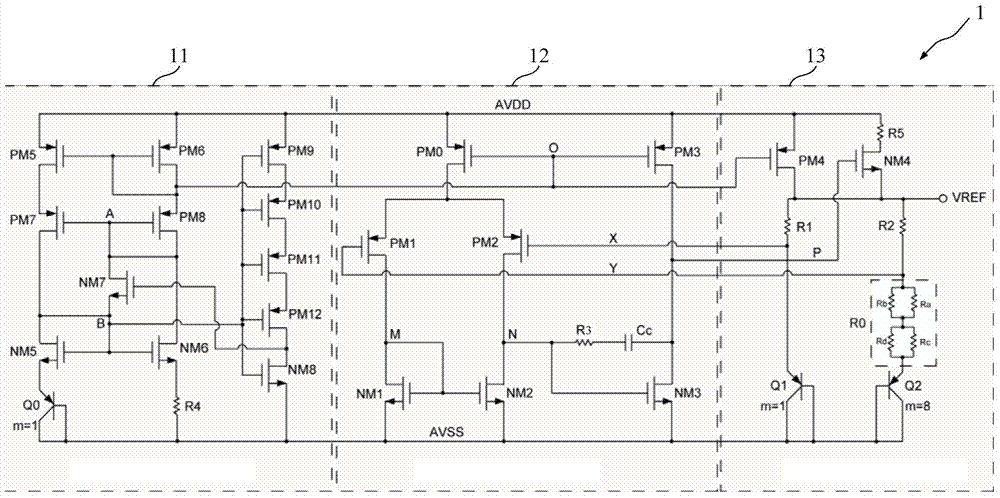
NMOS drive output band-gap reference circuit

A reference circuit and drive output technology, applied in the direction of adjusting electrical variables, control/regulation systems, instruments, etc., can solve problems such as large output load, large power consumption, and poor reliability of voltage sources, so as to improve reliability and drive ability , Improve the effect of resistance matching performance

Active Publication Date: 2015-06-17
VERISILICON MICROELECTRONICS SHANGHAI +3
View PDF4 Cites 8 Cited by
  • Summary
  • Abstract
  • Description
  • Claims
  • Application Information

AI Technical Summary

Problems solved by technology

[0006] In view of the shortcomings of the prior art described above, the purpose of the present invention is to provide an NMOS driven output bandgap reference circuit, which is used to solve the problem of large output load, large power consumption, and reliable voltage source of the bandgap reference circuit in the prior art. gender issues

Method used


Image

  • NMOS drive output band-gap reference circuit

Examples


Embodiment Construction

[0068] Embodiments of the present invention are described below through specific examples, and those skilled in the art can easily understand other advantages and effects of the present invention from the content disclosed in this specification. The present invention can also be implemented or applied through other different specific implementation modes, and various modifications or changes can be made to the details in this specification based on different viewpoints and applications without departing from the spirit of the present invention.

[0069] see figure 1 . It should be noted that the diagrams provided in this embodiment are only schematically illustrating the basic idea of ​​the present invention, and only the components related to the present invention are shown in the diagrams rather than the number, shape and shape of the components in actual implementation. Dimensional drawing, the type, quantity and proportion of each component can be changed arbitrarily duri...


PUM


Abstract

The invention provides an NMOS drive output band-gap reference circuit. The NMOS drive output band-gap reference circuit comprises a starting circuit module for providing a bias voltage, an operational amplifier used for fixing node voltages at the two feedback input ends of a band-gap reference module and the band-gap reference module used for generating a reference voltage with the zero-temperature coefficient; the starting circuit module provides the bias voltage for the operational amplifier and the band-gap reference module. According to the NMOS drive output band-gap reference circuit, an NMOS serves as output of the band-gap reference voltage, and the band-gap reference drive capacity is improved; a PMOS is used for starting the current of the circuit in a mirroring mode, hundreds of nA of current flows through a band-gap reference zero-temperature coefficient generation circuit, the band-gap reference starting capacity is strengthened, and the circuit reliability is improved. Unit resistors are connected in parallel or in series to be equivalent to a resistor R0, so that the resistance matching performance is improved, and the band-gap reference accuracy is optimized; the resistors are connected between an NMOS drive pipe and a power source in series, so that the electrostatic protection capacity of the circuit is improved.

Description

technical field [0001] The invention relates to the field of large-scale analog integrated circuit design, in particular to a bandgap reference circuit suitable for a strong drive capability and a current starting mechanism. Background technique [0002] The reference voltage source is the cornerstone of CMOS integrated circuit design, providing reference voltage for most analog circuits in the chip, such as digital-to-analog conversion (D / A Convertor) circuit, analog-to-digital conversion (A / D Convertor) circuit, phase-locked loop, power supply Management modules and comparators, etc. [0003] The output voltage of an ideal reference voltage source does not vary with changes in temperature, process, supply voltage, and load. The way to realize the reference voltage includes Zener tube, thermal voltage reference source, VBE reference source and bandgap reference source. Among them, the bandgap reference voltage source is widely used because of its advantages of compatibili...

Claims


Application Information

Patent Timeline
Patent Type & Authority Applications(China)
IPC IPC(8): G05F1/56
Inventor 朱彤刘军苏秀敏许明
Owner VERISILICON MICROELECTRONICS SHANGHAI
Learn More