
Shield station passing method of first passing large shield through station and then building air flue structure

A technology of shield tunneling and air duct, which is applied in tunnels, earthwork drilling, tunnel lining, etc., and can solve problems that affect the efficiency of shield tunneling, long construction periods, and complicated construction procedures.

Active Publication Date: 2015-06-17
BEIJING MUNICIPAL CONSTR +2
View PDF5 Cites 6 Cited by
  • Summary
  • Abstract
  • Description
  • Claims
  • Application Information

AI Technical Summary

Problems solved by technology

[0003] However, the air duct is an underground excavation large-section high-side wall structure, the construction process is complicated, and the construction period is long. Due to the fast excavation speed of the shield machine, the construction of the air duct of the station is restricted by factors such as ground demolition and pipeline relocation. It is difficult to meet the shield receiving and starting conditions required by the design, and the shield tunneling speed can only be slowed down or waited after arriving at the station, which affects the shield construction efficiency and the realization of the "hole opening goal"

Method used


Image

  • Shield station passing method of first passing large shield through station and then building air flue structure
  • Shield station passing method of first passing large shield through station and then building air flue structure
  • Shield station passing method of first passing large shield through station and then building air flue structure

Examples


Embodiment Construction

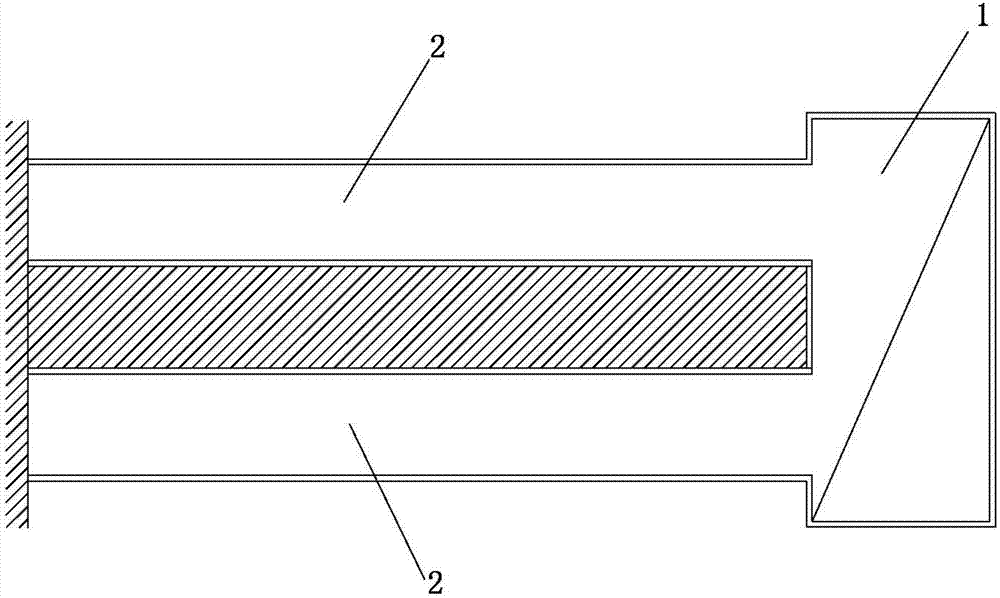
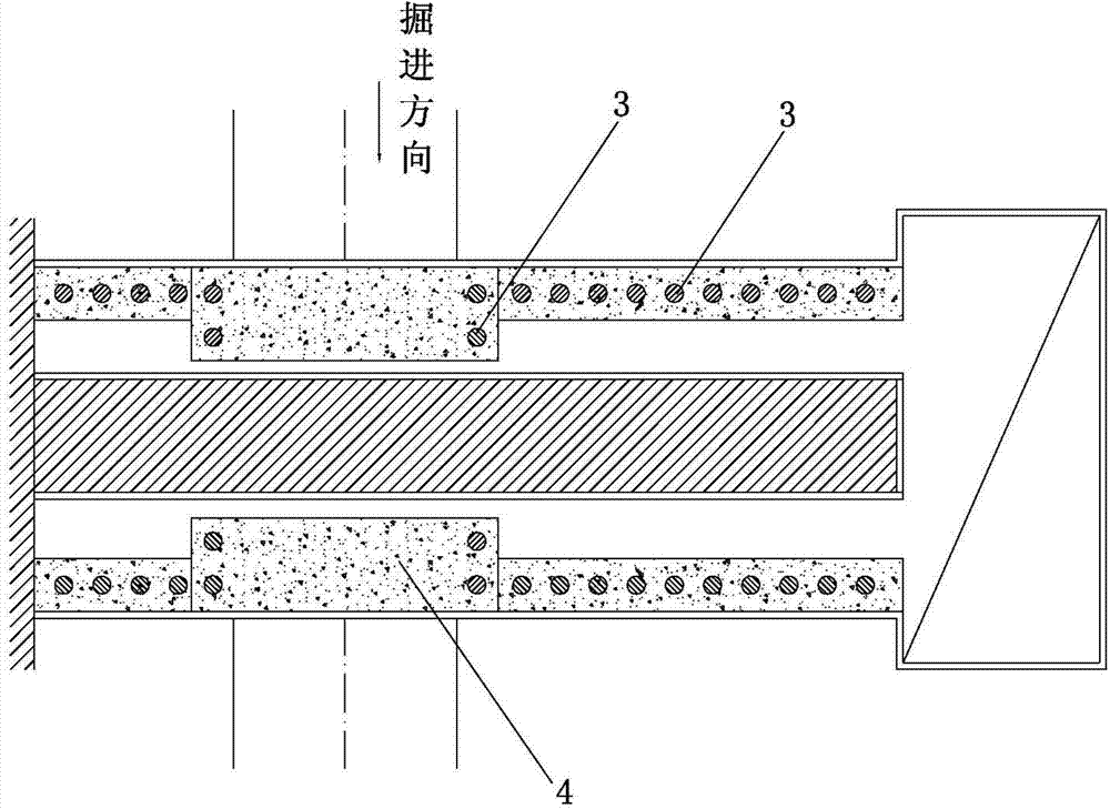
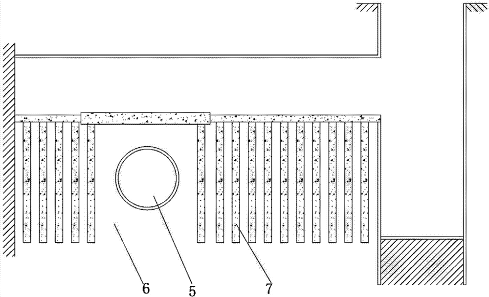
[0017] Please refer to the attached figure 1 To attach image 3 As shown, the present invention is a shield tunnel passing method in which a large shield passes the station first and then builds an air duct structure, which includes the following steps:

[0018] 1), such as figure 1 As shown, the vertical shaft 1 is used as the construction channel, and the horse head gate is opened on the side wall of the shaft, and the soil at the horse head gate is reinforced by grouting, and the three grids at the horse head gate are closely arranged. The small pilot tunnel 2 is excavated by the short step method, and the core soil is left. The step distance of each excavation is not greater than 0.75m. The soil in the arch part is reinforced by grouting with advanced small conduits, and the grouting grout is cement slurry. If the stratum contains water, it should be filled with cement-water glass double-fluid slurry;

[0019] 2), such as figure 2 As shown, the bored cast-in-place pil...


PUM


Abstract

The invention relates to a shield station passing method of first passing a large shield through a station and then building an air flue structure. The excavation of pilot tunnels arranged on two sides of an air flue is completed before a shield with a large diameter arrives the air flue, the cast-in-situ bored pile is conducted in the pilot tunnels, however, fender posts arranged in two sides of the pilot tunnels of a passing-through portion of the shield with the large diameter are not constructed temporarily, and the two sides of the pilot tunnels of a portion where the shield with the large diameter passes through the air flue are each additionally provided with one fender post, and the size of pilebolck crown beams of the portion where the shield with the large diameter passes through the air flue is increased. And then the shield with the large diameter passes through the air flue directly, and after the shield passes through the air flue, the earth excavation of the air flue and the secondary lining structure pouring are conducted. The shield station passing method of first passing the large shield through the station and then building the air flue structure can well solve the construction planning and preparing conflict between a running tunnel of a subway and the station, the shield can passes through the station air flue directly, the complete mutual independence between the running tunnel of the subway and the station can be guaranteed, the principal line of integral project planning and preparing is based on the running tunnel, and the aim of passing through the hole can be achieved as early as possible.

Description

【Technical field】 [0001] The invention relates to a construction method of a subway station, in particular to a shield tunnel passing method in which a large shield passes the station first and then constructs an air duct structure, and belongs to the technical field of rail transit engineering. 【Background technique】 [0002] Large-diameter shield tunneling is used for tunnels and stations in the subway section, forming a single-hole and double-track tunnel at one time, and the stations are expanded and excavated on the basis of shield tunnels. This construction method and engineering planning can better solve the difficulties encountered in the current conventional subway engineering planning. However, this kind of project planning method generally requires the completion of the construction of the air duct structure at both ends of the station, the strengthening of the ring beam construction, and the reinforcement of the soil on the side wall of the air duct before the sh...

Claims


Application Information

Patent Timeline
Patent Type & Authority Applications(China)
IPC IPC(8): E21D9/14E21D11/10
Inventor 汪挺乐贵平郭玉海李振东郑昊李爱民王全贤李建军李达孙世臣张丽丽黄齐武李学峥曾德光范长春孙颖
Owner BEIJING MUNICIPAL CONSTR
Learn More