
Metal die-casting die capable of internally and automatically cutting off sprue

An automatic cutting and die-casting mold technology, which is applied in the field of metal die-casting, can solve the problems of inconvenient exhaust, affecting the strength and appearance of products, and the inconvenience of removing residual materials from castings, etc.

Inactive Publication Date: 2015-06-17
牟维军
View PDF0 Cites 4 Cited by
  • Summary
  • Abstract
  • Description
  • Claims
  • Application Information

AI Technical Summary

Problems solved by technology

At the same time, the gating system consumes less material, the mold structure is simple and compact, and it is convenient to manufacture, but it is inconvenient to remove the gate, there are obvious gate traces on the product, the heat is concentrated at the gate, the cavity is sealed late, and the internal stress is large, which is easy to produce pores and Shrinkage cavity
(2) Spoke gate: It changes the entire circular feed into several small arc-shaped feeds. It is convenient to remove the gate, and the pouring system has less condensation, but the product is prone to weld marks, which affects the strength of the product. with appearance
However, the pressure loss is large, the pressure-holding and feeding effect is smaller than that of the direct gate, the exhaust is inconvenient, and defects such as weld lines, shrinkage cavities and pores are prone to occur.
(5) Fan-shaped gate: It is often used to form thin sheet castings with a large width. It has a short process and good effect, but due to the large gate size, it is inconvenient to remove the remaining material from the casting, and there are large traces on the outside of the casting.

Method used


Image

  • Metal die-casting die capable of internally and automatically cutting off sprue
  • Metal die-casting die capable of internally and automatically cutting off sprue
  • Metal die-casting die capable of internally and automatically cutting off sprue

Examples


Embodiment Construction

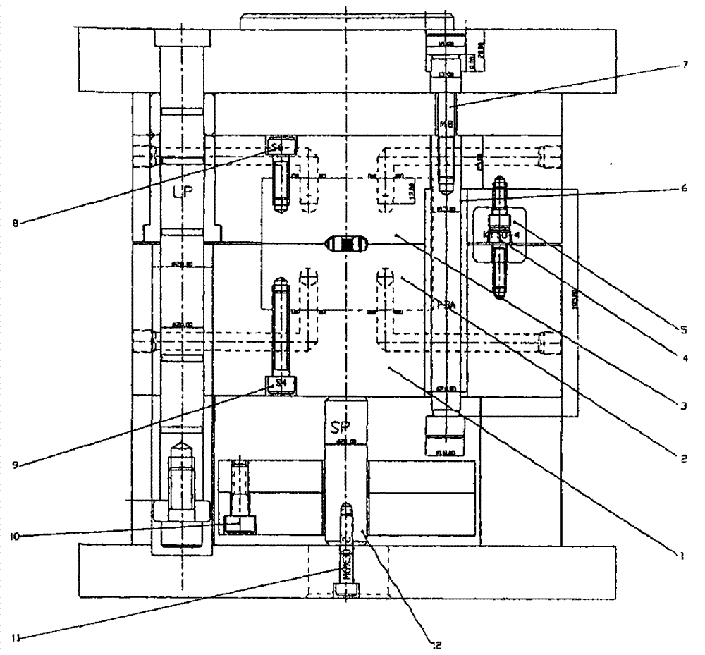
[0021] As shown in the figure, it is a metal die-casting mold that automatically cuts off the gate. In order to achieve the purpose of automatically cutting off the casting and the gating system in the mold, the fixed mold side of the mold adopts a three-plate structure, and the fixed mold seat plate on the fixed mold side The well-type main runner sleeve (22) is set on the top, the runner is set behind the fixed template, and then the gate connected with the casting is set behind the fixed template. (22) is provided with the pulling needle (21) that breaks gate. For the purpose of the mold coming out of the mold automatically after the gating system is cut off, the first pull rod (7) is set so that the first pull rod (7) drives the runner plate to push the remaining material of the gating system out of the mold when the mold is opened. For the flexible and reliable movement of the runner plate and the cavity plate, four guide posts are set on the fixed side of the mold to ens...


PUM


Abstract

The invention discloses a metal die-casting die capable of internally and automatically cutting off a sprue. The die is composed of a fixed clamping plate, a moving clamping plate, a stripper plate, a pull needle, pull rods, a guide column, a resin die opener, a sliding block and a pressing block. The first pull rod (7), the second pull rod (6), the resin die opener (18) and the pull needle (21) are communicated to form an automatic cut-off mechanism of a die gating system. The pull needle (21) and the stripper plate form a gating system freezing material disengagement device. A first ejector pin (15), a second ejector pin (33), a rack core (32), an ejector pin plate and an ejector pin fixing plate are communicated to form a die ejecting mechanism. An inclined guide column (26), an inclined pressing block (27), a sliding block (30) and a first spring (31) are communicated to form a die side face core-pulling mechanism. According to the metal die-casting die, the action is firm and reliable, pressure transfer is good, the automatic sprue shearing efficiency of the die is high, and by means of optimized module design, the structure is compact, and manufacturing, installation, debugging and maintenance are convenient.

Description

technical field [0001] The invention relates to metal die-casting molding, which is a metal die-casting mold for automatically cutting off gates in the mold. Background technique [0002] The gating system of the metal die-casting mold refers to the flow channel of the melt from the injection punch of the die-casting machine to the cavity. The requirements are: to introduce the melt into the cavity smoothly so that it fills the cavity as required; to make the gas in the cavity be discharged smoothly; during the process of filling the cavity and solidifying the melt, the pressure can be fully transmitted to the mold. Each part of the cavity to obtain die-casting parts with dense structure, clear shape and stable size. It can be seen that the importance of gating system design for metal die casting molds. Whether the design of the gating system is correct or not is the key to whether the die-casting can be carried out smoothly and whether high-quality die-castings can be obt...

Claims


Application Information

Patent Timeline
IPC IPC(8): B22D17/22
Inventor 牟维军
Owner 牟维军
Learn More