
X-ray CT device, image processing device and image processing method

An X-ray and energy technology, applied in image data processing, image enhancement, image analysis, etc., to solve problems such as inability to obtain data, data transmission time, increased reconstruction time, and large data volume.

Active Publication Date: 2017-08-25
TOSHIBA MEDICAL SYST CORP
View PDF4 Cites 0 Cited by
  • Summary
  • Abstract
  • Description
  • Claims
  • Application Information

AI Technical Summary

Problems solved by technology

However, if the energy discrimination is carried out carefully, the amount of data will become huge, and the data transmission time and reconstruction time will increase.
On the other hand, if energy identification is roughly performed, the data required for the identification of the substance of interest cannot be obtained

Method used


Image

  • X-ray CT device, image processing device and image processing method
  • X-ray CT device, image processing device and image processing method
  • X-ray CT device, image processing device and image processing method

Examples


no. 1 Embodiment approach

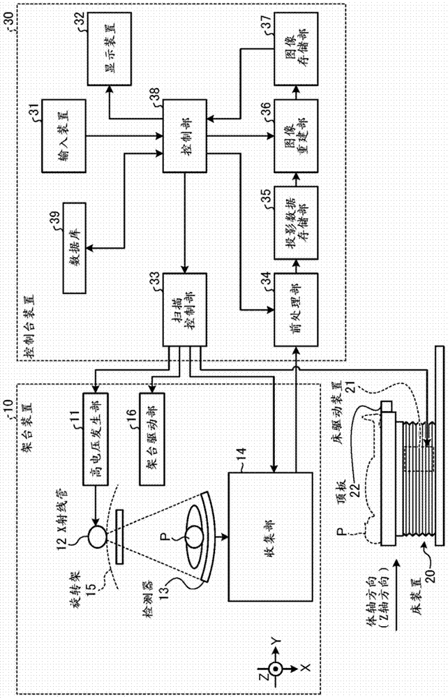
[0037] First, the configuration of the X-ray CT apparatus according to the first embodiment will be described. figure 1 It is a diagram showing a configuration example of the X-ray CT apparatus according to the first embodiment. Such as figure 1 As shown, the X-ray CT apparatus according to the first embodiment includes a gantry device 10 , a bed device 20 , and a console device 30 .

[0038] The gantry device 10 is a device that irradiates the subject P with X-rays and counts the X-rays transmitted through the subject P, and includes a high voltage generator 11, an X-ray tube 12, a detector 13, a collection unit 14, The rotating frame 15 and the frame drive unit 16 .

[0039] The rotating frame 15 is supported so that the X-ray tube 12 and the detector 13 face each other across the subject P, and rotates at a high speed on a circular orbit centered on the subject P by a stage driving unit 16 described later. circular frame.

[0040] The X-ray tube 12 is a vacuum tube that...

no. 2 Embodiment approach

[0146] The collection unit 14 according to the first embodiment needs to actively change the set energy division sets according to the control unit 38 to perform energy discrimination. That is, the collection unit 14 needs to dynamically change and perform energy discrimination using a plurality of thresholds that are changed according to the characteristic energy value of the substance to be processed.

[0147] In view of this, the second embodiment uses Figure 16 , Figure 17 as well as Figure 18 to explain. in, Figure 16 yes means figure 1 A diagram of the first configuration example of the detector and the collection unit shown, Figure 17 yes means figure 1 The figure of the second configuration example of the detector and the collection part shown, Figure 18 yes means figure 1 A diagram of the second configuration example of the detector and collection unit shown.

[0148] In addition, in the following description, for setting the use of Figure 10 The thre...


PUM


Abstract

An X-ray CT apparatus according to an embodiment includes a collection unit, a control unit, and an image reconstruction unit. The collection unit counts photons originating from X-rays transmitted through the subject, and collects a result of discriminating the energy of the counted photons as a count result. The control unit notifies the collection unit of the energy division sets set based on the X-ray absorption characteristics of the substance designated by the operator. The image reconstruction unit receives count results collected by the collection unit by assigning count values ​​to the plurality of energy discrimination domains set in the energy division set, and reconstructs image data using the received count results.

Description

technical field [0001] Embodiments of the present invention relate to an X-ray CT apparatus, an image processing apparatus, and an image processing method. Background technique [0002] In recent years, an X-ray CT apparatus that performs photon counting CT (Computed Tomography) using a photon counting type detector has been developed. Unlike an integrating type detector used in a conventional X-ray CT apparatus, a photon-counting detector outputs a signal capable of individually counting photons originating from X-rays transmitted through a subject. Therefore, in photon counting CT, an X-ray CT image with a high SN ratio (Signal per Noise) can be reconstructed. [0003] In addition, a signal output from a photon-counting detector can be used to measure (discriminate) the energy of each counted photon. Therefore, in photon counting CT, data collected by irradiating X-rays with one type of tube voltage can be divided into a plurality of energy components and imaged. For ex...

Claims


Application Information

Patent Timeline
Patent Type & Authority Patents(China)
IPC IPC(8): A61B6/03
CPCA61B6/032A61B6/4241A61B6/482A61B6/5205G06T11/005G06T2211/408G06T5/00G06T7/0012G06T2207/10081G06T2207/10116
Inventor 加藤彻及川大造中井宏章
Owner TOSHIBA MEDICAL SYST CORP
Learn More