
Magnetic resonance imaging device and image processing device

A magnetic resonance imaging and image technology, applied in magnetic resonance measurement, measurement device, measurement of magnetic variables, etc., can solve the problems of MR image quality deterioration and time-consuming, etc.

Active Publication Date: 2017-09-05
TOSHIBA MEDICAL SYST CORP
View PDF2 Cites 0 Cited by
  • Summary
  • Abstract
  • Description
  • Claims
  • Application Information

AI Technical Summary

Problems solved by technology

[0004] In the MRI apparatus, it is known to obtain the k-space data required for reconstruction by performing one-dimensional imaging repeatedly, but this imaging generally takes time.
In addition, it is also known that when the state of the specimen changes with time, the quality of the reconstructed MR image deteriorates.

Method used


Image

  • Magnetic resonance imaging device and image processing device
  • Magnetic resonance imaging device and image processing device
  • Magnetic resonance imaging device and image processing device

Examples


no. 1 Embodiment approach

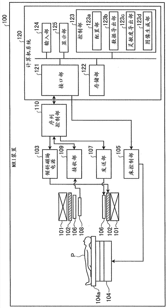
[0033] figure 1 It is a block diagram showing the MRI apparatus 100 according to the first embodiment. Such as figure 1 As shown, the MRI apparatus 100 includes a static magnetic field magnet 101, a gradient magnetic field coil 102, a gradient magnetic field power supply 103, a bed 104, a bed control unit 105, a transmitting coil 106, a transmitting unit 107, a receiving coil array 108, a receiving unit 109, and a sequence control unit 110. Computer system 120 (also referred to as "image processing device"). However, the MRI apparatus 100 does not include the subject P (for example, a human body).

[0034] The static magnetic field magnet 101 is a hollow cylindrical magnet that generates a uniform static magnetic field in the internal space. The static magnetic field magnet 101 is, for example, a permanent magnet, a superconducting magnet, or the like. The gradient magnetic field coil 102 is a coil formed in a hollow cylindrical shape, and is arranged inside the static magnetic...


PUM


Abstract

A magnetic resonance imaging apparatus (100) according to one embodiment includes an arranger (123a), a sensitivity deriver (123c), and an image generator (123d). The arranger (123a) arranges time-series data at a part of sampling points out of sampling points of a k-space determined based on an imaging parameter. The sensitivity deriver (123c) derives a sensitivity distribution in a time-space, in which the time-series data transformed in a time direction is expressed with a coefficient value, based on the time-series data. The image generator (123d) generates an image of the time-series data using the time-series data and the sensitivity distribution.

Description

Technical field [0001] The embodiment of the present invention relates to a magnetic resonance imaging apparatus and an image processing apparatus. Background technique [0002] Magnetic resonance imaging equipment (hereinafter referred to as MRI (Magnetic Resonance Imaging) equipment) uses hydrogen and other atoms placed in a magnetic field to selectively absorb and release electromagnetic waves of various frequencies depending on the type of atoms and magnetic field. It is a device that non-destructively visualizes the distribution of atoms inside the specimen with the properties of electromagnetic waves of the highest frequency. The signal obtained by measuring the electromagnetic wave emitted from the specimen by the coil and digitizing it is called k-space data. [0003] The k-space data is, for example, two-dimensional or three-dimensional data obtained by repeatedly performing one-dimensional imaging. The atomic distribution image inside the specimen is subjected to Fourier...

Claims


Application Information

Patent Timeline
Patent Type & Authority Patents(China)
IPC IPC(8): A61B5/055G01R33/32
CPCG01R33/561G01R33/5611G01R33/56509G01R33/385G01R33/4818
Inventor 竹岛秀则
Owner TOSHIBA MEDICAL SYST CORP
Learn More