Power-on protection circuits and electronic equipment

A technology for protecting circuits and resistors, which is applied in the field of microelectronics and can solve problems such as short voltage rise time, narrow dynamic range of output voltage, and breakdown

Active Publication Date: 2017-08-04
SHANGHAI IND U TECH RES INST
View PDF7 Cites 0 Cited by
  • Summary
  • Abstract
  • Description
  • Claims
  • Application Information

AI Technical Summary

Problems solved by technology

When the external power supply supplies power to the internal circuit, the voltage rise time is very short, which may cause the voltage of some nodes of the internal circuit to rise suddenly, causing some devices, such as diodes, triodes and MOS tubes, to be broken down or even burned out.
Therefore, usually in the power management module, a power-on protection circuit is required to provide a slowly rising voltage to the internal circuit to achieve the effect of protection, also known as soft start, but the dynamic range of the output voltage in the prior art is often relatively narrow

Method used


Image

  • Power-on protection circuits and electronic equipment
  • Power-on protection circuits and electronic equipment
  • Power-on protection circuits and electronic equipment

Examples


Embodiment Construction

[0035] The foregoing and other features of the present application will become apparent from the following description, taken with reference to the accompanying drawings. In the specification and drawings, specific embodiments of the present application are specifically disclosed, which indicate some embodiments in which the principles of the present application can be adopted. It should be understood that the present application is not limited to the described embodiments, on the contrary, the present application The application includes all amendments, variations and equivalents that come within the scope of the appended claims.

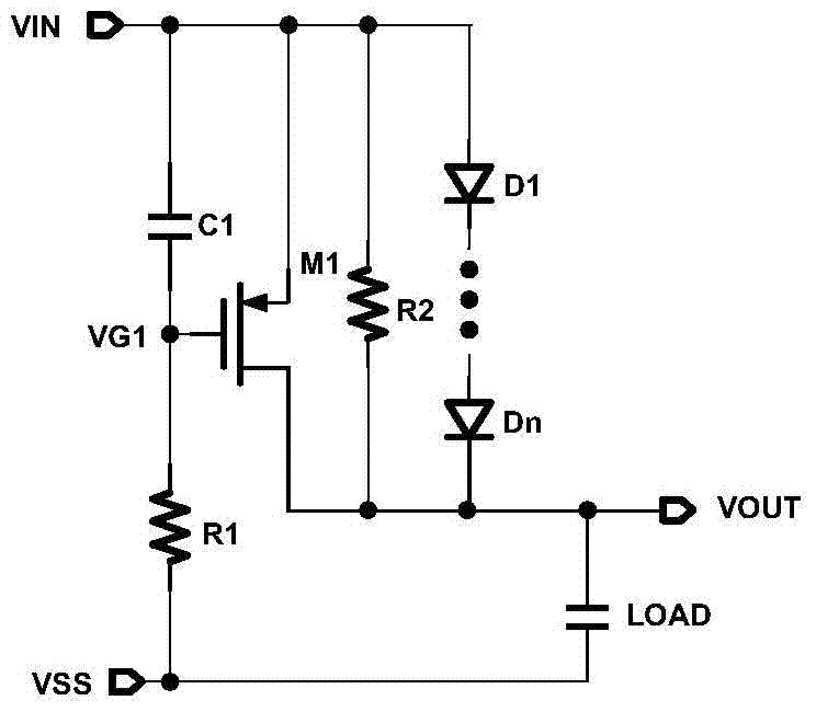
[0036] Such as figure 1 Shown: The power-on protection circuit includes a first-level protection circuit, wherein the first-level protection circuit includes a voltage input terminal, a voltage output terminal, and a ground terminal. The external power supply voltage signal is input from the input terminal, and the input voltage VIN of the input te...


PUM


Abstract

The present application provides a power-on protection circuit, in particular to a power-on protection circuit of a power management module. The power-on protection circuit may be a one-level or multi-level protection circuit. The protection circuit includes a voltage input terminal, a voltage output terminal, and a ground terminal, a first capacitor C1 and a first resistor R1 are sequentially connected between the voltage input terminal and the ground terminal; a parallel circuit composed of a first PMOS transistor M1, a second resistor R2, and a first diode string connected between the voltage input terminal and the voltage output terminal, wherein the source of the first PMOS transistor M1 is connected to the voltage input terminal, the drain is connected to the voltage output terminal, and the gate is connected to the first PMOS transistor M1 Between a capacitor C1 and the first resistor R1, a load is connected between the ground terminal and the voltage output terminal. The power-on protection circuit of this application has the characteristics of easy implementation, small chip area occupation, high reliability, and wide dynamic range. .

Description

technical field [0001] The present application relates to the field of microelectronic technology, in particular to a power-on protection circuit of a power management module and electronic equipment. Background technique [0002] In microelectronic circuit design, the power management module is an essential part of the system. When the external power supply supplies power to the internal circuit, the voltage rise time is very short, which may cause the voltage of some nodes of the internal circuit to rise suddenly, causing some devices, such as diodes, triodes and MOS tubes, to be broken down or even burned out. . Therefore, usually in the power management module, a power-on protection circuit is required to provide a slowly rising voltage to the internal circuit to achieve the effect of protection, also known as soft start, but the dynamic range of the output voltage in the prior art is often relatively narrow . [0003] The power-on protection circuit of the present ap...

Claims


Application Information

Patent Timeline
Patent Type & Authority Patents(China)
IPC IPC(8): H03K17/687
Inventor 郑晓一卢煜旻石雯杨澄思
Owner SHANGHAI IND U TECH RES INST
Why Eureka
Try Eureka