


Quick Research
Generate reliable direction feasibility study reports for your R&D in just a few steps.

Technical Q&A
Discover and master advanced knowledge NOW. Basics, ideas, possibilities, all at once.

Find Solutions
As an expert in R&D theories, this can generate solutions to your technical problems instantly.

Evaluate Feasibility
Analyze your overall solution with one click, know your potential R&D risks in advance.

Monitor Landscape
Get weekly tech updates, stay abreast of the latest tech innovations and key insights.
Ups secondary power-off circuit and secondary power-off method
A circuit and battery voltage technology, applied in the field of UPS, can solve the problems of affecting important load operation, shortening load delay time, affecting battery life, etc., to avoid large current discharge, increase battery life, and reduce costs.
- Summary
- Abstract
- Description
- Claims
- Application Information
AI Technical Summary
Problems solved by technology
Method used
Image

Examples
Embodiment
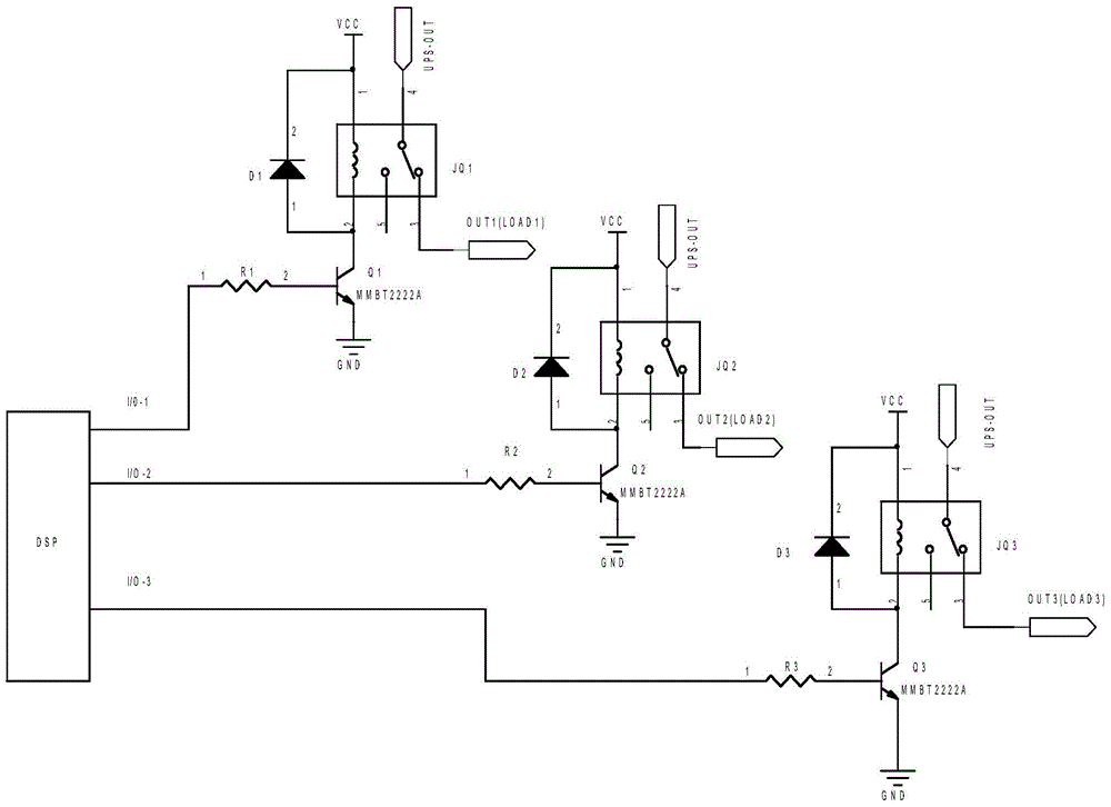
[0018] UPS secondary power-off circuit of the present invention, it comprises: some code switch I / 0-N, the input terminal of code switch I / 0-N is electrically connected with DSP chip, and output terminal is connected with resistance R N connection, the resistor R N Connect to the base of the transistor QN, the emitter of the transistor QN is grounded, the collector is connected to one end of the coil of the relay JQN, the other end of the coil is connected to the VCC terminal of the power supply, the normally closed contact 3 of the relay JQN is connected to the load, and the common terminal 4 is connected to the UPS output Terminal UPS-OUT, a diode D is connected in parallel to both ends of the coil of the relay JQN N ;The 0 bit setting of the DIP switch is: not limited by the UPS battery voltage, and the load will be disconnected after the UPS battery voltage is discharged; The corresponding load is disconnected.
[0019] The power-off method of the above-mentioned UPS sec...
Embodiment approach
[0022] refer to figure 1 , as an implementation of the invention, three load situations are cited:
[0023] The input terminal of the DIP switch I / 0-1 is electrically connected to the DSP chip, the output terminal is connected to the resistor R1, the resistor R1 is connected to the base of the transistor Q1, the emitter of the transistor Q1 is grounded, and the collector is connected to one end of the coil of the relay JQ1 , the other end of the coil is connected to the VCC end of the power supply, the normally closed contact 3 of the relay JQ1 is connected to the load, the common end 4 is connected to the UPS output end, and a diode D1 is connected in parallel to both ends of the coil of the relay JQ1; the 0 bit of the dial switch I / 0-1 Set to: not limited by the UPS battery voltage, the load will disconnect and work after the UPS battery voltage is discharged; 1 bit is set to: when the battery voltage drops to the respective threshold 10.5V, the UPS output will be disconnect...
PUM
 Abstract
Description
Claims
Application Information
 - R&D Engineer
- R&D Manager
- IP Professional
- Industry Leading Data Capabilities
- Powerful AI technology
- Patent DNA Extraction
Browse by: Latest US Patents, China's latest patents, Technical Efficacy Thesaurus, Application Domain, Technology Topic, Popular Technical Reports.
© 2024 PatSnap. All rights reserved.Legal|Privacy policy|Modern Slavery Act Transparency Statement|Sitemap|About US| Contact US: help@patsnap.com