Current stabilizer tube and manufacturing method thereof

A steady current tube, N-type technology, applied in semiconductor/solid-state device manufacturing, electrical components, circuits, etc., can solve problems such as increased pinch-off voltage, decreased reliability, and circuit burnout, to increase the conduction current and improve Reliability, effect of reducing pinch-off voltage

Inactive Publication Date: 2015-06-10
SHANGHAI HUAHONG GRACE SEMICON MFG CORP
View PDF4 Cites 0 Cited by
  • Summary
  • Abstract
  • Description
  • Claims
  • Application Information

AI Technical Summary

Problems solved by technology

[0009] Depend on figure 1 It can be seen that in the prior art, a higher vertical withstand voltage is achieved by adjusting the thickness of the P-type epitaxial layer 102; and to achieve a larger conduction current, it is usually necessary to increase the width of the vertical conductive channel, that is, it is necessary to increase two The spacing between the N-type regions 103, when the spacing between the N-type regions 103 increases, the drain electrode of the Zener tube needs to add a higher bias voltage to make the P-type epitaxial layer 102 in the bottom region of the vertical conductive channel increase. Complete depletion, that is, the pinch-off voltage will increase, and the increase of the pinch-off voltage will reduce the reliability and increase the possibility of the circuit being burned
That is to say, there is a contradiction between the conduction current and the pinch-off voltage in the existing structure. When the conduction current needs to be increased, the pinch-off voltage will inevitably increase, and it is impossible to achieve a large conduction current and a small pinch-off voltage at the same time.

Method used


Image

  • Current stabilizer tube and manufacturing method thereof
  • Current stabilizer tube and manufacturing method thereof
  • Current stabilizer tube and manufacturing method thereof

Examples


Embodiment Construction

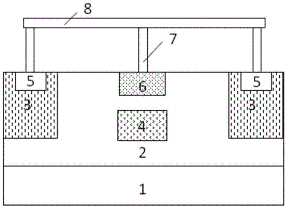
[0033] Such as figure 2 Shown is the structural diagram of the steady flow tube of the embodiment of the present invention; the steady flow tube of the embodiment of the present invention includes:

[0034] P-type heavily doped silicon substrate 1 .

[0035] The P-type epitaxial layer 2 is formed on the front surface of the silicon substrate 1 , the greater the thickness of the P-type epitaxial layer 2 , the greater the longitudinal withstand voltage of the ballast tube.

[0036] Two first N-type regions 3 formed on the surface of the P-type epitaxial layer 2, the two first N-type regions 3 are separated by a certain distance, and the two first N-type regions 3 are located between the two first N-type regions 3 The P-type epitaxial layer 2 forms the longitudinal conductive channel of the steady current tube. The larger the distance between the two first N-type regions 3, the wider the longitudinal conductive channel of the steady current tube. The larger the conduction curr...


PUM


Abstract

The invention discloses a current stabilizer tube comprising a P-type epitaxial layer, two first N-type areas, a longitudinal conduction trench and a third N-type area. The P-type epitaxial layer is formed on the front surface of a P+ silicon substrate. The first N-type areas are formed in the P-type epitaxial layer. The part, between the first N-type areas forms the longitudinal conduction trench. The third N-type area is formed in the P-type epitaxial layer in the bottom area of the longitudinal conduction trench. When a device operates, the third N-type area helps increase the ability to consume the P-type epitaxial layer in the bottom area of the longitudinal conduction trench, pinch-of voltage of the device can be reduced thereby; increase in the width of the longitudinal conduction trench leads to increase in conduction current; by adjusting the pinch-off voltage of the device through the third N-type area, the pinch-off voltage can be kept unchanged or lower while conduction current is increased, and reliability of the device is improved thereby. The invention further discloses a manufacturing method of the current stabilizer tube.

Description

technical field [0001] The invention relates to the field of semiconductor integrated circuit manufacturing, in particular to a steady current tube. The invention also relates to a method for manufacturing the steady flow tube. Background technique [0002] As a discrete device, the ballast tube is widely used because it can improve circuit stability and protect the circuit. Such as figure 1 Shown is the structural diagram of the existing steady flow tube; the existing steady flow tube includes: [0003] P-type heavily doped silicon substrate 101 . A P-type epitaxial layer 102 is formed on the front surface of the silicon substrate 101 , and the greater the thickness of the P-type epitaxial layer 102 , the greater the longitudinal withstand voltage of the ballast tube. [0004] Two N-type regions 103 formed on the surface of the P-type epitaxial layer 102, the P-type epitaxial layer 102 between the two N-type regions 103 constitute the vertical conductive channel of the ...

Claims


Application Information

Patent Timeline
IPC IPC(8): H01L29/78H01L29/06H01L21/336
CPCH01L29/0657H01L29/66409H01L29/78
Inventor 刘冬华段文婷钱文生
Owner SHANGHAI HUAHONG GRACE SEMICON MFG CORP
Why Eureka
Try Eureka