
Electronic current transformer transient transformation delay time measuring device and method

A current transformer and delay time technology, which is applied in the field of transient characteristic testing of electronic transformers, can solve the problem that the absolute delay time cannot replace the delay time, and the improvement of qualitative analysis performance cannot be greatly improved and cannot reflect Action time and other issues to achieve the effect of improving measurement accuracy, simple structure, and small size

Inactive Publication Date: 2015-06-10
STATE GRID CORP OF CHINA +2
View PDF4 Cites 18 Cited by
  • Summary
  • Abstract
  • Description
  • Claims
  • Application Information

AI Technical Summary

Problems solved by technology

Method 1 Since the characteristics of electronic current transformers in the transient state and the steady state process are very different, and the application of the current sampling value of the relay protection equipment in the transient state is different from that in the steady state, it is determined The absolute delay time in the steady state cannot replace the delay time in the transient state, and the reference effect is very limited
Method 2 The test of the entire set of delay time cannot reflect the action time of each individual device, and it will not play a big role in qualitative analysis and the improvement of the performance of each independent device

Method used


Image

  • Electronic current transformer transient transformation delay time measuring device and method
  • Electronic current transformer transient transformation delay time measuring device and method

Examples


Embodiment Construction

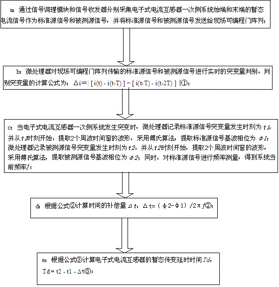
[0020] Such as figure 1 , 2 As shown, the present invention includes a signal conditioning module, an optical fiber signal transceiver, an analog-to-digital conversion module, a high-precision constant temperature crystal oscillator module, a field programmable gate array, a microprocessor and a display module, and the signal input terminal of the signal conditioning module is used for inputting standard Source signal, the signal output end of the signal conditioning module is connected to the first signal input end of the field programmable gate array through the analog-to-digital conversion module, and the second signal input end of the field programmable gate array is connected to the sending end of the optical fiber signal transceiver, and the optical fiber signal The receiving end of the transceiver is used to connect the measured source signal, the signal transmission end of the field programmable gate array is connected to the microprocessor, the microprocessor is conn...


PUM


Abstract

The invention discloses an electronic current transformer transient transformation delay time measuring device and method. The device comprises a signal conditioning module, an optical signal transceiver, an analog-to-digital conversion module, a high-precision constant-temperature crystal oscillator module, a field programmable gate array, a microprocessor and a display module, wherein the signal input end of the signal conditioning module is used for inputting a standard source signal, the signal output end of the signal conditioning module is connected with the first signal input end of the field programmable gate array through the analog-to-digital conversion module, the second signal input end of the field programmable gate array is connected with the transmitting end of the optical signal transceiver, the receiving end of the optical fiber transceiver is used for being connected with a to-be-measured source signal, the signal transmitting end of the field programmable gate array is connected with the microprocessor, the microprocessor is connected with the display module, and the high-precision constant-temperature crystal oscillator module is respectively connected with the analog-to-digital conversion module, the field programmable gate array and the microprocessor.

Description

technical field [0001] The invention relates to the field of transient characteristic testing of electronic transformers used in smart grids, in particular to a measuring device and method for transient transmission delay time of electronic current transformers. Background technique [0002] At present, electronic current transformers are widely used in smart grids. Interval layer equipment such as relay protection, metering, measurement and control, and fault recording are all based on the sampling values ​​of electronic current transformers to complete their respective automation functions. Electronic current transformers The steady-state characteristics and transient characteristics of the device directly affect the performance of the back-end bay layer equipment. Relay protection equipment is the key equipment for the safe and stable operation of the power system. When a fault occurs, it must be accurately judged and decided whether to act at the fastest speed. At this t...

Claims


Application Information

Patent Timeline
IPC IPC(8): G01R35/02
Inventor 吴春红刘磊马伟东李雷罗海冰马建胜石光赵勇汤汉松
Owner STATE GRID CORP OF CHINA
Learn More