


Quick Research
Generate reliable direction feasibility study reports for your R&D in just a few steps.

Technical Q&A
Discover and master advanced knowledge NOW. Basics, ideas, possibilities, all at once.

Find Solutions
As an expert in R&D theories, this can generate solutions to your technical problems instantly.

Evaluate Feasibility
Analyze your overall solution with one click, know your potential R&D risks in advance.

Monitor Landscape
Get weekly tech updates, stay abreast of the latest tech innovations and key insights.
Hemorheology detecting device
A technology of blood rheology and transmission devices, applied in the direction of measuring devices, flow characteristics, instruments, etc., can solve the problems of inconvenient use and operation, difficult to arrange, etc., and achieve the effect of simple structure
- Summary
- Abstract
- Description
- Claims
- Application Information
AI Technical Summary
Problems solved by technology
Method used
Image

Examples
Embodiment 1
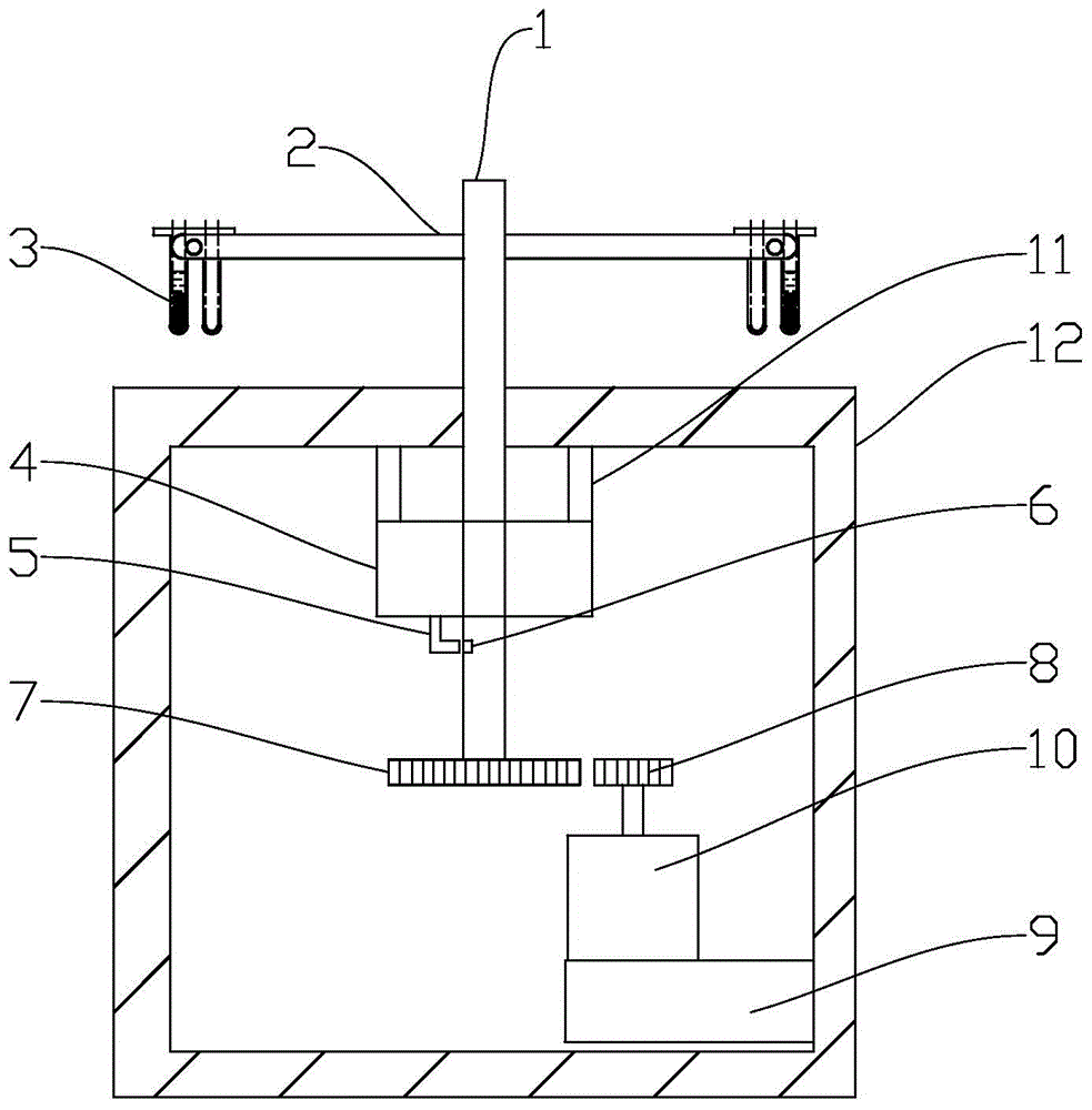
[0031] Embodiment one: if figure 1 As shown, in the device for blood rheology detection, the coaxial shaft on the main shaft of the centrifugal motor 4 is fixed with a stepping drive driven gear 7, and the output end of the main shaft of the stepping motor 10 is provided with a stepping driving driving gear. 8. The stepping driving driving gear 8 and the stepping driving driven gear 7 constitute the clutch transmission device. The stepping motor 10 and the stepping drive driving gear 8 are relatively fixed in position. The stepping motor 10 is installed on the moving part of a translation device 9 , and the fixed part of the translation device 9 is relatively fixed with the main support 12 . Also shown in the figure is a speed measuring device 5 for measuring the rotational speed of the main shaft of the centrifugal motor. A magnet 6 is bonded to the main shaft of the centrifugal motor, and the magnet 6 faces the speed measuring device. The two cooperate to detect the speed of...
Embodiment 2
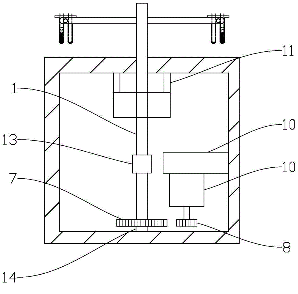
[0034] Embodiment two: if figure 2 As shown, in the device for blood rheology detection, the output end of the main shaft of the stepping motor 10 is also provided with a stepping drive driving gear 8, which cooperates with the stepping driving driving gear 8 to form a stepping drive slave of a clutch transmission. The gear 7 is arranged on a fixed shaft 14, and may be mounted on the fixed shaft through a bearing. The fixed shaft 14 is relatively fixed to the main bracket 12 ; the main shaft 1 of the centrifugal motor is arranged coaxially with the fixed shaft 14 and connected by a coupling 13 . The position of the stepper motor 10 and the stepping driving driving gear 8 is relatively fixed, and the stepper motor 10 is installed on the moving part of a translation device 9 , and the fixed part of the translation device 9 is relatively fixed with the main support 12 .
[0035]During high-speed centrifugation, the main shaft 1 of the centrifugal motor drives the coupling 13 an...
Embodiment 3
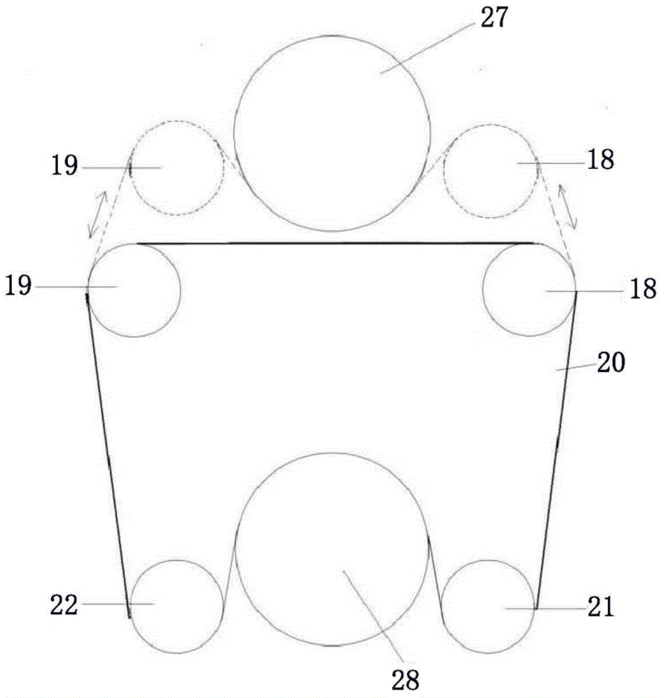
[0036] Embodiment three: as image 3 As shown, in this embodiment, the output end of the stepper motor 10 main shaft is provided with a stepping drive active synchronous pulley 28, and the synchronous belt 20 bypasses the stepping driving active synchronous pulley 28 and bypasses the first guide wheel 21, the second Two guide wheels 22, the first tensioner 18, the second tensioner 19. The step driving driven synchronous pulley 27 and the step driving driving synchronous pulley 28 and the synchronous belt 20 constituting the clutch type transmission device are arranged on the main shaft 1 of the centrifugal motor. The position of the stepper motor 10 and the stepping drive active synchronous pulley 28 is relatively fixed and relatively fixed with the main support 12; 12 is relatively fixed. When the translation device realizes that the synchronous belt 20 moves to the direction of the step-driven driven synchronous pulley 27, the distance between the two tensioners decreases,...
PUM
 Abstract
Description
Claims
Application Information
 - R&D Engineer
- R&D Manager
- IP Professional
- Industry Leading Data Capabilities
- Powerful AI technology
- Patent DNA Extraction
Browse by: Latest US Patents, China's latest patents, Technical Efficacy Thesaurus, Application Domain, Technology Topic, Popular Technical Reports.
© 2024 PatSnap. All rights reserved.Legal|Privacy policy|Modern Slavery Act Transparency Statement|Sitemap|About US| Contact US: help@patsnap.com