A laser online measurement system for particle size distribution of polluted flue gas

A particle size and laser technology, applied in particle and sedimentation analysis, measuring devices, particle size analysis, etc., to achieve the effect of improving efficiency and accurate measurement results

Inactive Publication Date: 2019-02-01
SHANDONG UNIV OF TECH
View PDF3 Cites 0 Cited by
  • Summary
  • Abstract
  • Description
  • Claims
  • Application Information

AI Technical Summary

Problems solved by technology

[0004] The purpose of the present invention is to provide a laser online measurement system for particle size distribution of polluted flue gas, which overcomes the existing PM2. Particle Size Distribution Curve

Method used


Image

  • A laser online measurement system for particle size distribution of polluted flue gas
  • A laser online measurement system for particle size distribution of polluted flue gas

Examples


Embodiment Construction

[0019] Specific embodiments of the present invention will be described below in conjunction with the accompanying drawings.

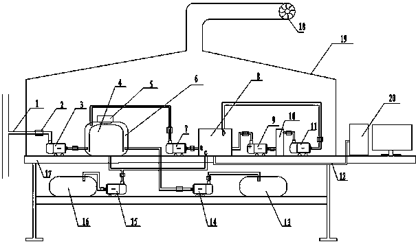
[0020] exist figure 1 In the example shown in , the frame 17 plays the role of fixed equipment, the first gas pump 3 is connected with the gas pipeline through the gas conduit 1, the gas flow regulating valve 2 is installed on the gas conduit, and the control system on the computer 20 controls When the gas pump is started or stopped, the first gas pump 3 sends the gas to be tested to the gas chamber 6, and there is a gas centrifuge 4 in the gas chamber. When the concentration of the gas to be tested is too high, the measurement result is obviously incorrect. At this time, the computer 20 will feed back the control signal to the fifth gas pump 14 and the centrifuge control module 5, the fifth gas pump 14 and the centrifuge will start, and the ammonia in the ammonia tank 13 will be sent into the gas chamber by the fifth gas pump 14 Mix with the sampled g...


PUM

PropertyMeasurementUnit
diameteraaaaaaaaaa
particle diameteraaaaaaaaaa

Abstract

The invention provides a laser on-line measurement system for the particle size distribution of polluted flue gas, which includes a gas conduit, a gas collection system, a laser measurement system and a computer, wherein the gas collection system is equipped with a gas pump, a gas flow regulating valve, and a gas centrifuge. The gas acquisition system sends the gas to be measured into the laser measurement system for measurement. In order to improve the measurement accuracy, this system adopts layered measurement technology. The finished gas passes through the gas particle filter to filter out particles with a diameter larger than 1 μm, and then sends the gas to the laser measurement system, uses the laser dynamic scattering method to measure the particle size distribution of the particle size smaller than 1 μm, and finally summarizes the data to the computer, using Relevant software and algorithm analysis and processing, draw the particle size distribution curve.

Description

technical field [0001] The invention provides a laser on-line measurement system for particle size distribution of polluted flue gas, which belongs to the technical field of on-line particle measurement. Background technique [0002] With the development of the economy and the gradual improvement of people's living standards, the country pays more and more attention to the quality of the environment, especially the quality of the air. The dust in the air mainly comes from heavy industries such as power generation, chemical industry, and metallurgy. Flue gas particles will be emitted during the process. At present, enterprises mainly use manual timing sampling to measure the quality of flue gas emissions. Some enterprises have given up the purification treatment of industrial waste gas for economic benefits. [0003] Fine particles can be suspended in the air for a long time and have an important impact on air quality. Studies have shown that fine particles are more harmful ...

Claims


Application Information

Patent Timeline
Patent Type & Authority Patents(China)
IPC IPC(8): G01N15/02
Inventor 郭帅申晋马立修王雅静刘伟陈文钢徐敏
Owner SHANDONG UNIV OF TECH
Why Eureka
Try Eureka